An instrument which is used to measure magnetic flux density is known as magnetometer. This instrument is also known as Gauss meter or Tesla meter since its output can be expressed in Gauss or Tesla.
Gauss is the unit of magnetic flux density in CGS system while Tesla is in SI system. The two units can be related as: 1 Tesla = 104 gauss.
- Magnetometers can also be used to measure the magnetization of a magnetic material, such as ferromagnetic material.
- They are widely used to detect magnetic anomalies in geophysical surveys and determine the Earth’s magnetic field.
- These instruments can also be used in military applications, such as to detect submarines.
- In addition, magnetometers can also work as very long range metal detectors. Their detection range is of tens of metres which is much greater than the two metre range of a conventional metal detector.
However, these instruments can only detect the magnetic materials. The different types of magnetometers are induction coil magnetometer, fluxgate magnetometer, and Hall-effect magnetometer.
Induction Coil Magnetometer
An induction coil magnetometer consists of a coil placed in a changing magnetic field which results in an induced voltage at the terminals of the coil. The coil consists of a ferromagnetic core which concentrates the magnetic field that increases the level of induced voltage. However, it may limit the frequency of the field to be measured. An induction coil magnetometer is shown in Figure 1.
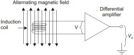
The induced voltage, denoted by V, is in direct proportion to the number of turns in the coil, N and the time rate change of the magnetic flux.
We can calculate the value of induced EMF in the coil with the help of the following relation:
VRMS = 4.44fN ɸm
ɸm = VRMS ÷ 4.44fN
Where ɸm is the peak value of the flux, f is the frequency of the sinusoidal signal and N is the number of turns in the coil.
The relation between the magnetic flux F and magnetic flux density B is given by the relation:
B = ɸ/A
Where A is the cross-sectional area of the coil measured in square metre (m2 ), flux F is in webers (Wb), and the magnetic flux density B is given in Teslas (T).
Fluxgate Magnetometer
The induction coil magnetometer works for the alternating magnetic field. However, when both the coil and magnetic field are stationary, there will be no induced voltage in the coil. Thus, it may be concluded that for a steady-state magnetic field, the induction coil magnetometer cannot be used to determine its strength.
In fluxgate magnetometer, an excitation field is used which disturbs the effect of steady-state magnetic field on a sense or secondary coil. Due to this, a voltage is induced which is in proportion to the flux density in the static field.
The fluxgates are rugged, compact, low in cost, and have low power consumption.
There are two types of fluxgate magnetometers to be discussed in detail, namely, twin-rod fluxgate and ring-core fluxgate.
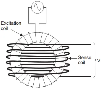
Twin-rod fluxgate: As the name suggests, this fluxgate consists of two bar-shaped magnets placed adjacent to each other. Each of the magnets is provided with an excitation coil through which an alternating current flows as shown in Figure 2.
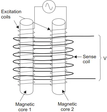
The alternating current in the coils drives the two rods into positive and negative saturation, that is, if one rod is south at the top, the other will be north at the top and vice versa. The sense coil produces an output voltage on changing the flux of the core.
When no external static magnetic field is applied, the flux in one core cancels the flux in the other core due to opposite polarity. As a result, no voltage is induced in the secondary coil in this case. This is illustrated by the waveforms in Figure 3.
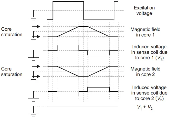
While the cores are saturated, no voltage will be induced in the sense coil. However, during the saturation, voltages get induced in the sense coil from the excitation coil. These voltages are represented as V1 and V2 in the figure, which are of equal magnitude but opposite polarity. Therefore, these voltages cancel out each other leaving output from the sense coil to be zero.
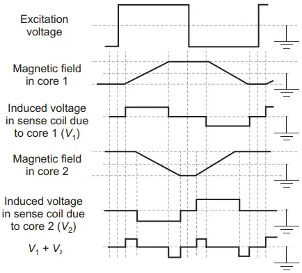
Now, consider the case when an external magnetic field is applied by placing the fluxgate magnetometer in a static magnetic field. This static field drives the core having same polarity as that of the static field deeper into saturation whereas it opposes the core with opposite polarity. This results in a net flux imbalance in the two rods as well as unsymmetricity in the induced voltages V1 and V2.
As a consequence, an output voltage proportional to the magnetic flux density of the static magnetic field will be generated in the sense coil. This output is equal to the algebraic sum of V1 and V2. The waveforms are shown in Figure 4.
The magnitude of the output voltage so produced depends upon the rate of change of the flux which further depends upon the excitation voltage, number of turns in the sense coil, geometry of the sense coil, and magnetic permeability of the core.
The difference in the flux densities in the core arises due to flux density of the static field and determines the width of the output pulse.
So, we may say that the static magnetic field modulates the output of the fluxgate where the modulation is pulse width modulation. This static field flux density can be obtained using an integrator.
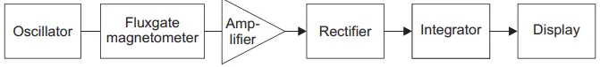
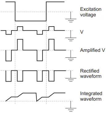
The circuit for obtaining static field flux density along with waveforms at various stages is shown in Figure 5.
Here the output, before applying to the integrator must be amplified and rectified. Therefore, an amplifier and a rectifier are connected prior to the integrator.
Ring-core fluxgate: Ring-core fluxgate magnetometer consists of a ring-shaped core on which the excitation coil is wound in a torroidal fashion as shown in Figure 6.
Its operation is similar to that of twin-rod fluxgate. The twin-rod fluxgate magnetometer can be converted into a ring-core fluxgate magnetometer by closing the magnetic circuit at top and bottom with two rods.
Application of Fluxgate Magnetometer: The major application of a fluxgate magnetometer is to align it with the Earth’s magnetic field since it can measure the flux density of a static field and can also determine the direction and polarity of the field if it is inverted.
When a fluxgate is perfectly aligned with the static magnetic field to be measured, it produces the highest output voltage and if a change in the alignment of the fluxgate occurs, the output gets reduced.
Here, it is to be noted that as long as the field frequency is smaller than the excitation frequency, fluxgates can also be used to study alternating magnetic fields.
Hall-effect Magnetometer
When a strip of current-carrying conductor is subjected to a transverse magnetic field, a voltage is produced at the edges of the conductor which is perpendicular to the direction of both magnetic field and current. This phenomenon is known as Hall-effect.
The magnitude of the output voltage VH is proportional to the magnetic flux density B, current I, the material (generally semiconductor) used for the conductor and its dimensions. Thus, the output voltage VH is expressed as:
VH = KH BI sinθ
Where KH is known as Hall-effect coefficient and represents the combined effect of conductor’s dimensions and material, and θ is the angle between the direction of the magnetic field and the Hall-effect device.
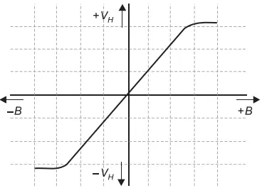
The relation between output voltage VH and magnetic flux density B is represented in Figure 7. It can be noticed that the output voltage VH varies linearly with the magnetic flux density B up to a saturation level in either positive or negative direction, provided the current is held constant.
The polarity of the magnetic field determines the polarity of the output voltage VH when the direction of the current does not change.
Generally, a differential amplifier is used to amplify the output voltage from Hall-effect device for measurement as it is of the order of microvolts or millivolts range.
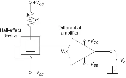
A variable resistor is also used to adjust the value of current, however, it must be held constant at a particular value (see Figure 8).
Hall-effect magnetometers are used in applications with large magnetic field strengths, for example, as anti-lock braking systems in cars.