Multimeter is a device used to measure multiple quantities in a circuit. The digital multimeters (abbreviated as DMM) have many advantages in comparison to analog multimeters. DMMs give highly precise results, have high input impedance, much greater resolution and are smaller in size. They indicate overload and show negative sign for reverse connection, and can switch to various appropriate ranges also. Since this multimeter does not have a pointer to indicate the measured values, there is no observation error.
Block Diagram of Digital Multimeter
The main components used in a digital multimeter are shown in Figure 1. This block diagram represents the various steps involved in the working of a digital multimeter. The analog input enters the internal circuit through the probes in a waveform.
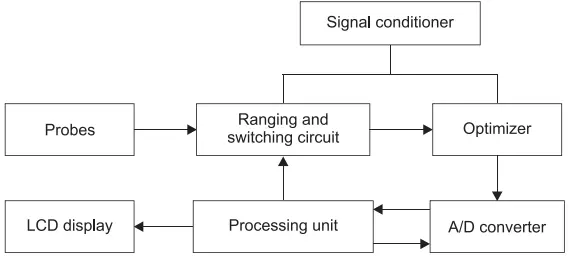
After selecting a suitable range via ranging and switching circuit, the signal is then passed through a signal conditioner which performs the conditioning of the signal.
The various linear processes involved in signal conditioning are attenuation, integration, addition, subtraction, differentiation, and amplification as well as some non-linear processes like modulation, demodulation, clipping, clamping, squaring, sampling so that a faithful reproduction of the input signal can be obtained.
The signal is then measured by the measurement circuitry after which it is optimized by the optimizer and then forwarded to an analog-to-digital converter (that is, ADC) which converts the input voltage into its discrete equivalent. Usually, dual slope integration method is used in ADC for the conversion.
The processing unit takes the input from the output of ADC, decodes the magnitude of the values and then passes it onto the LCD display.
Digital multimeter is a voltage sensing meter. Most of the measurements done are voltage based. The current and resistance measurements are performed where each quantity is converted to voltage and the DVM circuitry measures the voltage.
Current Measurement
Two different circuits can be utilized to measure current in a digital multimeter.
One of them is based on voltage measurement. In this circuit, a digital voltmeter is used to measure the voltage drop across a constant resistance when the current is passed through it.
In the other circuit, the measurement of current is done by frequency method. A current-to-frequency converter is shown in Figure 2. The circuit consists of an integrator, pulse generator, comparator, and a current source.
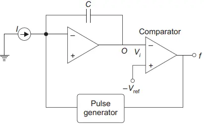
The capacitor C of the integrating circuit is charged by the constant current source I and the integrator output is compared with the reference voltage – Vref by applying it to a comparator as shown in the figure.
When the applied voltage Vi is less than the reference voltage – Vref, the pulse generator gets triggered and the capacitor gets discharged. The comparator results in a frequency output which is proportional to the current. The current can be measured in different ranges given as:
0 – 10 mA, 10 mA – 100 mA, 100 mA – 1 A, and 1 A – 10 A.
Resistance Measurement
The circuit used for measuring resistance consists of a constant current source I which is generated by a voltage source as shown in Figure 3.
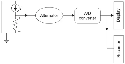
For this, the internal resistance of the voltage source is increased to a very high value. The current is then passed through the resistance to be determined and the voltage drop across it is measured by DVM to calculate the value of resistance.
Specifications of Digital Multimeter
Specifications of a DMM define the functions and ranges of a quantity, such as voltage, current, and resistance. Figure 4 shows a basic digital multimeter consisting of a single function switch (that is, rotary selector) which can be rotated to select any one of the available functions. The switch can make any one of these selections: OFF, V (dc), V (ac), A (dc), A (ac), and Ω (resistance).
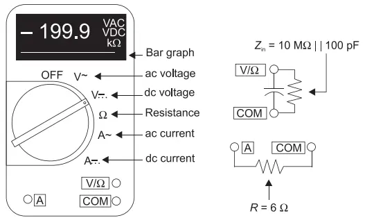
Three terminals for connecting the cords are also provided which are: COM (common), V /Ω (volts/ohm), and A (current). The A terminal is used for measuring current whereas V/Ω terminal is used for measuring both voltage and resistance. The COM terminal is always connected to the ground for all measurements. Auto ranging and auto polarity indication features are also provided in the DMM.
The ranges of various measurements are given as follows.
- V (dc): 0 to 1.999 / 19.99 / 199.9 / 1000 V
- V (ac): 0 to 1.999 / 19.99 / 199.9 / 750 V
- A (dc): 0 to 1.999 / 19.99 / 199.9 / 1999 mA
- A (ac): 0 to 1.999 / 19.99 / 199.9 / 1999 mA
- Ω : 0 to 199.9 Ω, 0 to 1.999 / 19.99 / 199.9 k Ω, 0 to 1.999 / 19.99 M Ω
Other than these, some more specifications are also provided for DMM as:
- Burden voltage for current measurements: 6 mV / mA
- Frequency range for AC measurements: 40 to 500 Hz
- Input impedance: 10 MΩ || 100 pF
When the multimeter is used as an ammeter, the terminal voltage drop is indicated by the burden voltage. For example, if the burden voltage is 6 mV / mA, the ammeter resistance is 6 Ω, then the terminal voltage drop VT for a current of 500 mA will be:
VT = 500 mA × 6 mV / mA
VT = 3 V
The effect of this voltage drop must be considered on the circuit under test. Here, it should be noted that the instrument must be operated in the specified frequency range of 40 Hz to 500 Hz for AC measurements on low cost DMMs and the measurements should not be done outside this frequency range by this instrument.
The basic DC accuracy of the multimeter is given to be ± 0.7% of the reading or even better. The type of measurement being made affects the accuracy of the multimeter. Accuracy of digital instruments is given as ± (0.5% rdg + 1 d) or it can be expressed as (0.5 + 1). Here, rdg means reading, thus 0.5% rdg means 0.5% of the reading while, 1 d refers to the least significant (extreme right numeral) digit of the display.
We have considered the most basic type of DMM and discussed its features. Other than this, many more DMMs are also available, namely bench-type DMM, and high performance hand-held DMM. The range of such DMMs can be extended using high-voltage, current, and frequency probes.
In addition, these instruments have many more features that include measuring frequency, duty cycle, decibel, conductance, capacitance, and true rms value.