Testing of Circuit Breakers
An equipment when designed to certain specifications and is fabricated, needs testing for its performance. The general design is tried and the results of such tests are conducted on one selected breaker and are thus applicable to all others of identical construction. These tests are called the type tests. These tests are classified as follows:
1. Short circuit tests:
- Making capacity test.
- Breaking capacity test.
- Short-time current test.
- Operating duty test
2. Dielectric tests:
- Power frequency test: (a) One minute dry withstand test. (b) One minute wet withstand test.
- Impulse voltage dry withstand test.
3. Thermal test.
4. Mechanical test
Once a particular design is found satisfactory, a large number of similar C.B.s are manufactured for marketing. Every piece of C.B. is then tested before putting into service. These tests are known as routine tests. With these tests, it is possible to find out if incorrect assembly or inferior quality material has been used for proven design equipment. These tests are classified as:
- operation tests,
- millivolt drop tests,
- power frequency voltage tests at the manufacturer’s premises, and
- power frequency voltage tests after erection on site.
We will discuss first the type tests. In that also we will discuss the short circuit tests after the other three tests.
Dielectric Tests
The general dielectric characteristics of any circuit breaker or switchgear unit depend upon the basic design i.e. clearances, bushing materials, etc. upon correctness and accuracy in assembly, and upon the quality of materials used.
For a C.B. these factors are checked from the viewpoint of their ability to withstand over voltages at the normal service voltage and abnormal voltages during lightning or other phenomenon. The test voltage is applied for one minute between
- phases with the breaker closed,
- phases and earth with C.B. open, and
- across the terminals with the breaker open.
With this, the breaker must not flash over or puncture. These tests are normally made on indoor switchgear. For such C.B.s the impulse tests generally are unnecessary because it is not exposed to impulse voltage of a very high order.
The high-frequency switching surges do occur but the effect of these in cable systems used for indoor switchgear is found to be safely withstood by the switchgear if it has withstood the normal frequency test.
Since the outdoor switchgear is electrically exposed, they will be subjected to overvoltages caused by lightning. The effect of these voltages is much more serious than the power frequency voltages in service. Therefore, this class of switchgear is subjected in addition to power frequency tests, and the impulse voltage tests.
The test voltage should be a standard 1/50 µ sec wave, the peak value of which is specified according to the rated voltage of the breaker. A higher impulse voltage is specified for non-effectively grounded systems than for solidly grounded systems. The test voltages are applied between
- each pole and earth in turn with the breaker closed and remaining phases earthed, and
- between all terminals on one side of the breaker and all the other terminals earthed, with the breaker open.
The specified voltages are withstand values i.e. the breaker should not flash over for 10 applications of the wave. Normally this test is carried out with waves of both polarities.
The wet dielectric test is used for outdoor switchgear. In this, the external insulation is sprayed for two minutes while the rated service voltage is applied; the test overvoltage is then maintained for 30 seconds during which no flashover should occur. The effect of rain on external insulation is partly beneficial, insofar as the surface is thereby cleaned, but is also harmful if the rain contains impurities.
Thermal Tests
These tests are made to check the thermal behavior of the breakers. In this test, the rated current through all three phases of the switchgear is passed continuously for a period long enough to achieve steady-state conditions. Temperature readings are obtained using thermocouples whose hot junctions are placed in appropriate positions.
The temperature rise above the ambient of conductors, must normally not exceed 40°C when the rated normal current is less than 800 amps and 50°C if it is 800 amps and above.
An additional requirement in the type test is the measurement of the contact resistances between the isolating contacts and between the moving and fixed contacts. These points are generally the main sources of excessive heat generation.
The voltage drop across the breaker pole is measured for different values of d.c. current which is a measure of the resistance of current carrying parts and hence that of contacts.
Mechanical Tests
A C.B. must open and close at the correct speed and perform such operations without mechanical failure. The breaker mechanism is, therefore, subjected to a mechanical endurance type test involving repeated opening and closing of the breaker.
B.S. 116: 1952 requires 500 such operations without failure and with no adjustment of the mechanism. Some manufacturers feel that as many as 20,000 operations may be reached before any useful information regarding the possible causes of failure may be obtained.
A resulting change in the material or dimensions of a particular component may considerably improve the life and efficiency of the mechanism.
Short Circuit Tests
These tests are carried out in short circuit testing stations to prove the ratings of the C.B.s. Before discussing the tests it is proper to discuss the short circuit testing stations. There are two types of testing stations; (i) field type, and (ii) laboratory type.
In the case of field-type stations the power required for testing is directly taken from a large power system. The breaker to be tested is connected to the system. Whereas this method of testing is economical for high voltage C.B.s it suffers from the following drawbacks:
- The tests cannot be repeatedly carried out for research and development as it disturbs the whole network.
- The power available depends upon the location of the testing stations, loading conditions, installed capacity, etc.
- Test conditions like the desired recovery voltage, the RRRV, etc. cannot be achieved conveniently.
In case of laboratory testing the power required for testing is provided by specially designed generators. This method has the following advantages:
- Test conditions such as current, voltage, power factor, and restriking voltages can be controlled accurately.
- Several indirect testing methods can be used.
- Tests can be repeated and hence research and development on the design is possible.
The limitations of this method are the cost and the limited power availability for testing the breakers.
Short Circuit Test Plants
The essential components of a typical test plant are represented in Fig. 1. The short-circuit power is supplied by specially designed short-circuit generators driven by induction motors. The magnitude of voltage can be varied by adjusting the excitation of the generator or the transformer ratio.
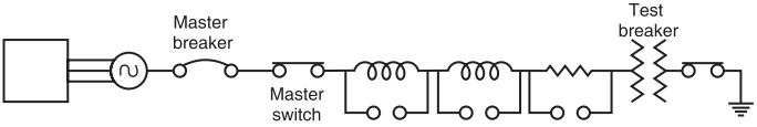
A plant master breaker is available to interrupt the test short circuit current if the test breaker should fail. Initiation of the short circuit may be by the master breaker, but is always done by a making switch which is specially designed for closing on very heavy currents but never called upon to break currents.
The generator winding may be arranged for either star or delta connection according to the voltage required; by further dividing the winding into two sections which may be connected in series or parallel, a choice of four voltages is available.
In addition to this, the use of resistors and reactors in series gives a wide range of current and power factors. The generator, transformer, and reactors are housed together, usually in the building accommodating the test cells.
Generator: The short circuit generator is different in design from the conventional power station. The capacity of these generators may be of the order of 2000 MVA and very rigid bracing of the conductors and coil ends is necessary because of possible high electromagnetic forces. The limiting factor for the maximum output current is the electromagnetic force. Since the operation of the generator is intermittent, this need not be very efficient. The reduction of ventilation enables the main flux to be increased and permits the inclusion of extra coil end supports. The machine’s reactance is reduced to a minimum.
Immediately before the actual closing of the making switch the generator driving motor is switched out and the short circuit energy is taken from the kinetic energy of the generator set. This is done to avoid any disturbance to the system during a short circuit.
However, in this case, it is necessary to compensate for the decrement in generator voltage corresponding to the diminishing generator speed during the test. This is achieved by adjusting the generator field excitation to increase at a suitable rate during the short circuit period.
Resistors and Reactors: The resistors are used to control the p.f. of the current and to control the rate of decay of d.c. component of current. There are several coils per phase and by combinations of series and parallel connections, the desired value of resistance and/or reactance can be obtained.
Capacitors: These are used for breaking line charging currents and for controlling the rate of re-striking voltage.
Short Circuit Transformers: The leakage reactance of the transformer is low to withstand repeated short circuits. Since they are in use intermittently, they do not pose any cooling problems. For voltage higher than the generated voltages, usually banks of single-phase transformers are employed.
In the short circuit station at Bhopal, there are three single-phase units each of 11 kV/76 kV. The normal rating is 30 MVA but their short circuit capacity is 475 MVA.
Master C.B.s: These breakers are provided as back up which will operate, should the breaker under test fail to operate. This breaker is normally air blast type and the capacity is more than the breaker under test. After every test, it isolates the test breaker from the supply and can handle the full short circuit of the test circuit.
Make Switch: The make switch is closed after other switches are closed. The closing of the switch is fast, sure, and without chatter. To avoid bouncing and hence welding of contacts, a high air pressure is maintained in the chamber. The closing speed is high so that the contacts are fully closed before the short circuit current reaches its peak value.
Test Procedure
Before the test is performed all the components are adjusted to suitable values to obtain desired values of voltage, current, rate of rise of restriking voltage, p.f. etc. The measuring circuits are connected and oscillograph loops are calibrated.
During the test, several operations are performed in a sequence in a short time of the order of 0.2 sec. This is done with the help of a drum switch with several pairs of contacts which is rotated with a motor. This drum when rotated closes and opens several control circuits according to a certain sequence.
In one of the breaking capacity tests, the following sequence was observed:
- After running the motor to a speed the supply is switched off.
- Impulse excitation is switched on.
- Master C.B. is closed.
- The oscillograph is switched on.
- Make switch is closed.
- C.B. under test is opened.
- Master C.B. is opened.
- The exciter circuit is switched off.
The circuit for direct test is shown in Fig. 2
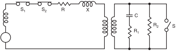
Here XG = generator reactance; S1 and S2 are master and make switches respectively. R and X are the resistance and reactance for limiting the current and control of p.f.; T is the transformer; C, R1, and R2 are the circuit for adjusting the restriking voltage.
For testing, the breaking capacity of the breaker under test, master and breaker under test are closed first. A short circuit is applied by closing the making switch. The breaker under test is opened at the desired moment and the breaking current is determined from the oscillograph as explained earlier.
For making the capacity test the master and the make switches are closed first and a short circuit is applied by closing the breaker under test. The making current is determined from the oscillograph as explained earlier.
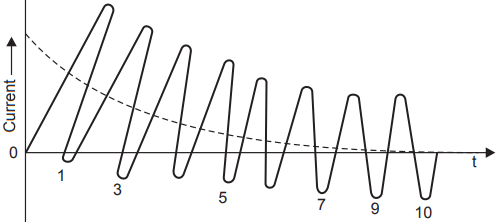
- For the short-time current test, the current is passed through the breaker for a short time say 1 second, and the oscillograph is taken as shown in Fig. 3. From the oscillograph the equivalent r.m.s. value of short-time current is obtained as follows:
- The time interval 0 to T is divided into 10 equal parts marked as 0, 1, 2 …, 9, 10.
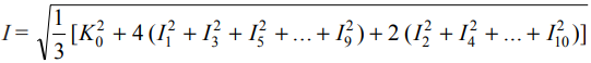
- Let the r.m.s. value of currents at these instants be I0 , I 1 , I2 , …, I9 , I10 (asymmetrical values). From these values, the r.m.s. value of short-time current is calculated using the Simpson formula.
Operating duty tests are performed according to standard specifications unless the duty is marked on the rating plate of the breaker. The tests according to specifications are:
(i) B—3′—B—3′—B at 10% of rated symmetrical breaking capacity;
(ii) B—3′—B—3′—B at 30% of rated symmetrical breaking capacity;
(iii) B—3′—B—3′—B at 60% of rated symmetrical breaking capacity;
(iv) B—3′—MB—3′—MB at not less than 100% of rated symmetrical breaking capacity and not less than 100% of rated making capacity.
Test duty may be performed as two separate duties as follows:
- M—3′—M (Make test);
- B—3′—B—3′—B (Break test)
(v) B—3′—B—3′—B at not less than 100% rated asymmetrical breaking capacity.
Here B and M represent breaking and making operations respectively. MB denotes the making operation followed by the breaking operation without any intentional time lag. 3′ denotes the time in minutes between successive operations of an operating duty.