Testing of Power Capacitors
Power capacitors are an integral part of the modern power system. These are used to control the voltage profile of the system. The following tests are carried out on shunt power capacitors (IS 2834):
Routine Tests
Routine tests are carried out on all capacitors at the manufacturer’s premises. During testing, the capacitor should not break down, behave abnormally, or show any visible deterioration.
1. Test for Output: Ammeter and Voltmeter can be used to measure the kVAr and capacitance of the capacitor. The kVAr calculated should not differ by more than –5 to +10% of the specified value for capacitor units and 0 to 10% for capacitor banks. The a.c. supply used for testing the capacitor should have a frequency between 40 Hz to 60 Hz, preferably as near as possible to the rated frequency and the harmonics should be minimum.
2. Test between Terminals: Every capacitor is subjected to one of the following two tests for 10 secs:
(a) D.C. test: the test voltage being Vt = 4.3 V0
(b) A.C. test: Vt = 2.15 V0
Where V0 is the RMS value of the voltage between terminals which in the test connection gives the same dielectric stress in the capacitor element as the rated voltage Vn gives in normal service.
3. Test between Line Terminals and Container (For capacitor units): An a.c. voltage of value specified in column 2 of Table 1 is applied between the terminals (short-circuited) of the capacitor unit and its container and is maintained for one minute, no damage to the capacitor should be observed.
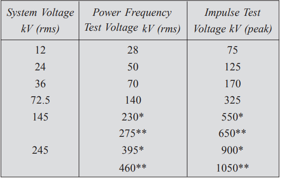
Figures with a single star represent values corresponding to reduced insulation level (Effectively grounded system) and with double star full insulation level (non-effectively grounded system).
4. IR Test: The insulation resistance of the test capacitor is measured with the help of a megger. The megger is connected between one terminal of the capacitor and the container. The test voltage shall be d.c. voltage not less than 500 volts and the acceptable value of IR is more than 50 megohms.
5. Test for efficiency of Discharge Device: To provide safety to personnel who would be working on the capacitors, it is desirable to connect very high resistance across the terminals of the capacitor so that they get discharged in about a few seconds after the supply is switched off.
The residual capacitor voltage after the supply voltage is switched off should be reduced to 50 volts in less than one minute if the capacitor is rated up to 650 volts and 5 minutes if the capacitor is rated for a voltage more than 650 volts.
A d.c. voltage √2 × RMS rated voltage of the capacitor is applied across the parallel combination of R and C. Where C is the capacitance of the capacitor under test and R is the high resistance connected across the capacitor. The supply is switched off and the fall in voltage across the capacitor as a function of time is recorded.
If C is in microfarads and R in ohms, the time to discharge to 50 volts can be calculated from the formula
t = 2.3 × 10⁻⁶ CR (log10V – 1.7) secs
Where V is the rated RMS voltage of the capacitor in volts.
Type Tests
The type tests are carried out only once by the manufacturer to prove that the design of the capacitor complies with the design requirements:
1. Dielectric Loss Angle Test (p.f. test): High voltage schering bridge is used to measure dielectric power factor. The voltage applied is the rated voltage and at temperatures 27°C ± 2°C. The value of the loss angle tan δ should not be more than 10% of the value agreed to between the manufacturer and the purchaser and it should not exceed 0.0035 for mineral oil impregnants and 0.005 for chlorinated impregnants.
2. Test for Capacitor Loss: The capacitor loss includes the dielectric loss of the capacitor and the V2/R loss in the discharge resistance which is permanently connected. The dielectric loss can be evaluated from the loss angle as obtained in the previous test and V2/R loss can also be calculated. The total power loss should not be more than 10% of the value agreed to between the manufacturer and consumer.
3. Stability Test: The capacitor is placed in an enclosure whose temperature is maintained at ±2°C above the maximum working temperature for 48 hours. The loss angle is measured after 16 hours, 24 hours, and 48 hours using High voltage Schering Bridge at rated frequency and at a voltage 1.2 times the rated voltage.
If the respective values of loss angle are tan δ1, tan δ2, and tan δ3, these values should satisfy the following relations (any of them):
(a) tan δ1 + tan δ2 ≤ 2 tan δ2 < 2.1 tan δ1
(b) tan δ1 ≥ tan δ2 ≥ tan δ3
4. Impulse voltage test between terminal and container: The capacitor is subjected to impulse voltage of 1/50 µ sec. Wave and magnitude as stipulated in column 3 of Table 6.1. Five impulses of either polarity should be applied between the terminals (joined together) and the container. It should withstand this voltage without causing any flashovers.