Testing of Transformer
A transformer is one of the most expensive and important equipment in the power system. If it is not suitably designed its failure may cause a lengthy and costly outage. Therefore, it is very important to be cautious while designing its insulation, so that it can withstand transient over voltage both due to switching and lightning.
The high voltage testing of transformers is, therefore, very important and will be discussed here. Other tests like temperature rise, short circuit, open circuit, etc. are not considered here. However, these can be found in the relevant standard specification.
Impulse Testing of Transformer
The impulse level of a transformer is determined by the breakdown voltage of its minor insulation (Insulation between turn and between windings), the breakdown voltage of its major insulation (insulation between windings and tank), and the flash-over voltage of its bushings or a combination of these. The impulse characteristics of internal insulation in a transformer differ from flash over in air in two main respects.
Firstly the impulse ratio of the transformer insulation is higher (varies from 2.1 to 2.2) than that of bushing (1.5 for bushings, insulators, etc.). Secondly, the impulse breakdown of transformer insulation is practically constant and is independent of the time of application of impulse voltage.
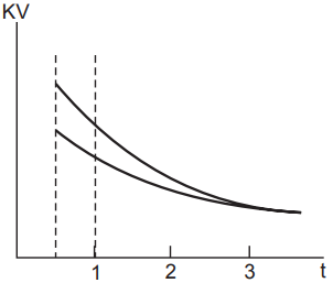
Fig. 1 shows that after three microseconds, the flashover voltage is substantially constant. The voltage stress between the turns of the same winding and between different windings of the transformer depends upon the steepness of the surge wavefront. The voltage stress may further get aggravated by the piling-up action of the wave if the length of the surge wave is large.
In fact, due to the high steepness of the surge waves, the first few turns of the winding are overstressed and that is why the modern practice is to provide extra insulation to the first few turns of the winding. Fig. 2 shows the equivalent circuit of a transformer winding for impulse voltage.
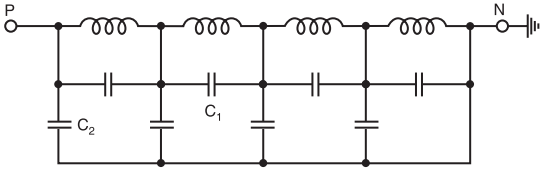
Here C1 represents inter-turn capacitance and C2 capacitance between winding and the ground (tank). For the minor insulation will be able to withstand the impulse voltage, the winding is subjected to a chopped impulse wave of higher peak voltage than the full wave. This chopped wave is produced by a flashover of a rod gap or bushing in parallel with the transformer insulation. The chopping time is usually 3 to 6 microseconds.
While impulse voltage is applied between one phase and ground, high voltages would be induced in the secondary of the transformer. To avoid this, the secondary windings are short-circuited and finally connected to the ground.
The short-circuiting, however, decreases the impedance of the transformer and hence poses a problem in adjusting the wave front and wave tail timings of the wave. Also, the minimum value of the impulse capacitance required is given by
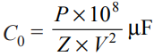
Where P = rated MVA of the transformer; Z = percent impedance of the transformer; V = rated voltage of the transformer.
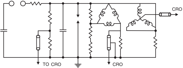
Fig. 3 shows the arrangement of the transformer for impulse testing. CRO forms an integral part of the transformer impulse testing circuit. It is required to record waveforms of the applied voltage and current through the winding under test.
Impulse testing consists of the following steps:
- Application of impulse of magnitude 75% of the Basic Impulse Level (BIL) of the transformer under test.
- One full wave of 100% of BIL.
- Two chopped waves of 115% of BIL.
- One full wave of 100% BIL and
- One full wave of 75% of BIL.
During impulse testing, the fault can be located by general observation like noise in the tank or smoke or bubbles in the breather. If there is a fault, it appears on the Oscilloscope as a partial or complete collapse of the applied voltage. A study of the waveform of the neutral current also indicated the type of fault. If an arc occurs between the turns or turns to the ground, a train of high-frequency pulses is seen on the oscilloscope, and the wave shape of the impulse changes. If it is a partial discharge only, high-frequency oscillations are observed but no change in wave shape occurs.
The bushing forms an important and integral part of transformer insulation. Therefore, its impulse flashover must be carefully investigated. The impulse strength of the transformer winding is the same for either polarity of wave whereas the flash over voltage for bushing is different for different polarity.
The manufacturer, however, while specifying the impulse strength of the transformer takes into consideration the overall impulse characteristic of the transformer.
Partial Discharge Test
To determine whether there is a deterioration or not of the insulation used in the transformer, this test is carried out. The test is carried out on the windings of the transformer to assess the magnitude of discharges. The shape of the discharge is an indication of the nature and severity of the defect in the insulation.
The measurements are to be made at all the terminals of the transformer and it is estimated that if the apparent measured charge exceeds 104 pico-coulombs, the discharge magnitude is considered to be severe and the transformer insulation should be so designed that the discharge measurement should be much below the value of 104 pico-coulombs.
Testing of Bushings
Bushings are an integral component of high-voltage machines. A bushing is used to bring high-voltage conductors through the grounded tank or body of the electrical equipment without excessive potential gradients between the conductor and the edge of the hole in the body. The bushing extends into the surface of the oil at one end and the other end is carried above the tank to a height sufficient to prevent breakdown due to surface leakage. The following tests are carried out on bushings:
1. Power Factor Test: The bushing is installed as in service or immersed in oil. The high-voltage terminal of the bushing is connected to the high-voltage terminal of the Schering Bridge and the tank or earth portion of the bushing is connected to the detector of the bridge. The capacitance and p.f. of the bushing are measured at different voltages as specified in the relevant specification and the capacitance and p.f. should be within the range specified.
2. Impulse Withstand Test: The bushing is subjected to impulse waves of either polarity and magnitude as specified in the standard specification. Five consecutive full waves of the standard waveform (1/50 µ sec.) are applied and if two of them cause flashover, the bushing is said to be defective. If only one flashover occurs, ten additional applications are made. If no flashover occurs, the bushing is said to have passed the test.
3. Chopped Wave and Switching Surge: Test Chopped wave and switching surge of appropriate duration tests are carried out on high voltage bushings. The procedure is identical to the one given in (2) above.
4. Partial Discharge Test: To determine whether there is a deterioration or not of the insulation used in the bushing, this test is carried out. The shape of the discharge is an indication of the nature and severity of the defect in the bushing. This is considered to be a routine test for high-voltage bushings.
5. Visible Discharge Test at Power Frequency: The test is carried out to ascertain whether the given bushing will give rise to ratio interference or not during operation. The test is carried out in a dark room. The voltage as specified is applied to the bushing (IS 2099). No discharge other than that from the grading rings or arcing horns should be visible.
6. Power Frequency Flash Over or Puncture Test (Under Oil): The bushing is either immersed fully in oil or is installed as in service condition. This test is carried out to ascertain that the internal breakdown strength of the bushing is 15% more than the power frequency momentary dry withstand test value.