Signal Generators
A signal generator is an instrument that provides a controlled output waveform or signal for use in testing, aligning or in measurements on other circuits or equipment. The signal generators can be classified into the following categories:-
1. Audio generators 2. Function generators 3. Pulse generators 4. RF generators 5. Frequency synthesizers 6. Other signal generators.
Audio Generators
The audio generators covers the frequency range 20 Hz to 20 kHz, although few models produce signals up to 100 kHz. Audio generators always produce pure sine waves and most also produce square waves.
They uses a 600 Ω output impedance and produce output levels from −40 dB mW to + 4 dB mW. Two methods of frequency selection are typically used in audio signal generators – continuous and step.
On the continuous type of a dial, we turn a knob to the desired frequency. Many such audio generators have a scale that reads 20 to 200 (or alternatively 2 to 20) and a range selector switch determines whether the output frequencies will be 20 to 200 Hz, 200 to 2000 Hz or 2000 to 20,000 Hz.
In a step-tuned generator, these controls are replaced by a rotary or pushbutton switch bank. As many as four decode switches might be used, although three is a more common number. These will be marked 0 through 100, 0 through 10 and 0.1 through 1.0 in decade steps.
A multiplier switch determines whether the actual frequency will be X1, X10, X100 or X1000 the frequency indicated on the selector switches.
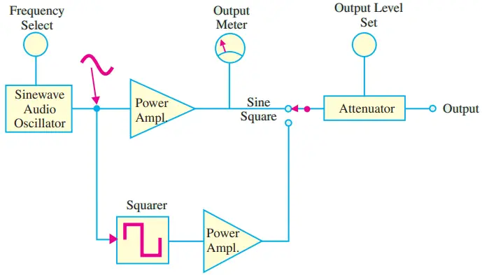
Fig. 1 shows a block diagram of an audio signal generator. The audio oscillator section is usually an RC phase-shift oscillator (or a Wien Bridge oscillator) circuit.
A power amplifier stage provides buffering between the load and the oscillator and it develops the output signal amplitude. The ac voltmeter at the output is strictly optional, but in some models it is used with a level control to set precisely the input signal to the attenuator. Not all quality audio signal generators use this feature.
So the lack of an ac output meter is not, in itself, indication of quality. In some models, an audio digital frequency counter is used ahead of the attenuator to provide digital display of the output frequency.
Applications: The audio generators are basically used to test the amplitude and frequency response of audio amplifiers.
Function Generators
These generators typically, cover at least the same frequency range as audio signal generators (i.e. 20 Hz to 20 kHz) but most modern designs have extended frequency ranges. A very common frequency range for function generators is 0.01 Hz to 3 MHz.
The major difference between a function generator and an audio generator is in the number of output waveforms. The audio signal generator produces only sine waves and square waves.
While almost all function generators produce these basic waveforms plus triangular waves. Besides this, some function generators also produce sawtooth, pulse and non-symmetrical square waves.
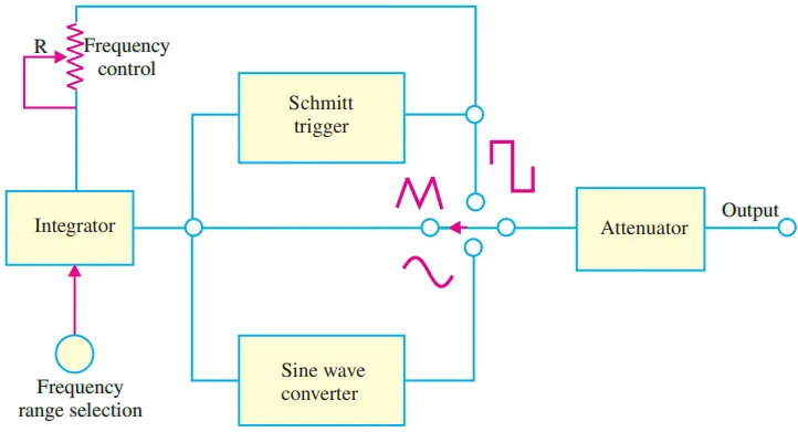
Fig. 2 shows a simple block diagram of a function generator.
The major parts of a function generator are schmitt trigger, integrator, sine-wave converter and an attenuator.
The schmitt trigger converts a slowly varying input signal to a square wave signal. This square wave signal is available at the output as well as it is also connected to the integrator as an input through a potentiometer (R).
The potentiometer is used to adjust the frequency of the output signal. The frequency range is adjusted by selecting the appropriate capacitor connected in the integrator circuit. The sine-wave converter is a six-level (or more) diode-resistor loading circuit.
Applications: The function generator is an essential equipment for an electronic laboratory to generate signals to test a variety of analog and digital system during the design phase as well as to trouble shoot such systems.
The function generators can be employed in a variety of applications in the area of product design, training, manufacturing production test, field repair, bench calibration and repair, laboratory and research, and education. Mainly they are used for testing amplifiers, filter and digital circuits.
Pulse Generators
Fig. 3 shows the block diagram of a pulse generator. As seen, an astable multivibrator generates square waves. This is used to trigger monostable multivibrator (i.e. one-shot). The pulse repetition rate is set by the square-wave frequency.
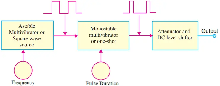
The one-shot triggers on the leading edge of the square-wave and produces one output pulse for each input cycle. The duration of each output pulse is set by the on-time of the one-shot. It may be very short or may approach the period of the square wave. The attenuator facilities output amplitude control and dc level shifting.
A typical pulse generator will allow the user to select the repetition rate, duration, amplitude and number of output pulses to be output in a given burst. The most common frequency range is from 1 Hz to 50 MHz. The pulse width is adjustable from 10 ns to over 10 ms and the output is variable from 3 mV to 30 V.
Applications: The pulse generators are used extensively to test memory circuits, shift registers, counters, other digital components, subsystems and systems.
RF Generators
A radio frequency (RF) signal generator has a sinusoidal output with a frequency somewhere in the range of 100 kHz to 40 GHz region.
Fig. 4 shows the block diagram of an RF generator. As seen, the instrument consists of an RF oscillator, an amplifier, a calibrated attenuator and an output level meter.The RF oscillator has a continuous frequency control and a frequency range switch, to set the output to any desired frequency.
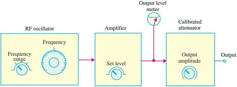
The amplifier includes an output amplitude control. This allows the voltage applied to the attenuator to be set to a calibration point on the output level meter. The output level must always be reset to this calibration point every time the frequency is changed. This is necessary to ensure that the output voltage levels are correct, as indicated on the calibrated attenuator. The oscillator circuit used in an RF generator is usually either a Hartley Oscillator or Colpitts oscillator.
Most RF signal generators include facilities for amplitude modulation and frequency modulation of the output. Switches are provided on the front panel to allow the user to select no modulation as well as internal or external A M or FM modulation.
It may be noted that each section of the RF generator is shielded by enclosing it in a metal box. The whole system is then completely shielded. The purpose of shielding is
- to prevent RF interference between the components and
- to prevent the emission of RF energy from any point except the output terminals.
As a matter of fact, even the power line is decoupled by means of RF chokes and capacitors to prevent RF emission from it.
Applications: The RF signal generators are widely used in the area of radar and communication, research and development laboratories, education and training, electromagnetic interference (EMI) testing and material testing. Their main applications are:-
- To perform variety of tests on radio transmitters and receivers.
- To test the amplitude and frequency response of RF amplifiers during the design phase.
Frequency Synthesizer
It is another type of RF generator that uses phase-locked loop (PLL) to generate output frequencies over a wide range. The most common range is from 1 MHz to 160 MHz.
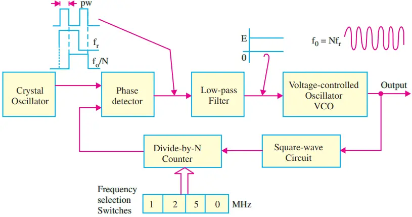
Fig. 5 shows a simple block diagram of a frequency synthesizer. As seen, the major components of the frequency synthesizer are voltage controlled oscillator (VCO), divide-by-N counter, phase detector, crystal oscillator, low-pass filter and a square-wave circuit.
The output of the crystal oscillator (a reference frequency, fr), is fed into one input of a phase detector. The other input of a phase detector has another square-wave applied to it as shown in the figure. The frequencies of these two square waves are identical but there is a phase difference (φ) between them.
The output of the phase detector is a pulse waveform with pulse width controlled by the phase difference. The output of the phase detector is applied to the low-pass filter which converts it into a dc voltage, E. The dc voltage, E is used as the control voltage for the VCO and it determines the output frequency of VCO.
The output of VCO is fed to a circuit that converts it into a square wave for triggering a digital divide-by-N counter. The divide-by-N counter divides the VCO frequency by a number set by a bank of switches.
These switches may be push buttons with digital readouts or they may be thumb-wheel type which indicate their position numerically. The switches are connected in such a way that the displayed number is the factor N by which the output frequency is divided before being applied to the phase detector. The switches allow the user to obtain frequency which is any integer multiple of the crystal oscillator frequency.
Applications: The frequency synthesizer is used in almost same areas as the RF signal generators.
Other Signal Generators
There are some signal generators that do not fit well in various pre-established categories. Some of these signal generators are as discussed below:-
1. RF Markers: These devices are usually crystal controlled and have a fixed output frequency for use as a reference. These are used to calibrate TV signals.
2. Digitally Programmable Test Oscillators: These instruments can have extremely wide frequency range although some versions have much narrow range also. The set frequency can be programmed through the front panel keypad or via a computer interface input such as IEEE-488 general purpose interface bus (commonly known as GPIB).
3. Arbitrary Waveform Generators: These instruments allow the user to design and generate virtually any desired waveform. The arbitrary waveform generator is quite useful to perform a variety of tests on communication equipment.
For example, a modulated signal that varies over the entire bandwidth and amplitude range of the equipment shown in Fig. 6 could be created for testing purpose.
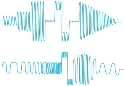
Noise could also be superimposed upon the signal and gaps might be introduced between waveform bursts, to investigate the response of the system. Once such a waveform has been designed, it could be stored in the instrument memory and can be recalled repeatedly for production testing.
Applications: The arbitrary waveform generators are used extensively in the following areas:-
- Communications design and test for producing (a) arbitrary IF based signals and (b) standard waveforms for communication.
- Mixed signal design and test.
- Disk drive read/write design and test.
- Real word simulations.
- High-speed low filter data and clock pulse generation.