Cathode Ray Tube – CRT
It is the ‘heart’ of an oscilloscope and is very similar to the picture tube in a television set.
Construction of CRT
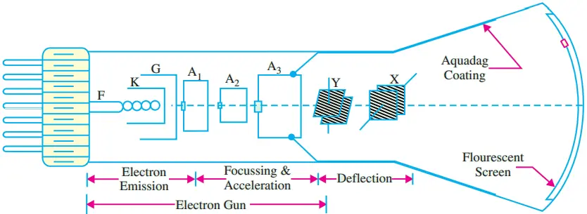
The cross-sectional view of a general purpose electrostatic deflection CRT is shwon in Fig. 1. Its four major components are:-
- An electron gun for producing a stream of electrons.
- Focussing and accelerating anodes for producing a narrow and sharply-focussed beam of electrons.
- Horizontal and vertical deflecting plates for controlling the path of the beam.
- An evacuated glass envelope with a phosphorescent screen which produces bright spot when struck by a high-velocity electron beam.
As shown, a CRT is a self-contained unit like any electron tube with a base through which leads are brought out for different pins.
Electron Gun Assembly
The electron gun assembly consists of an indirectly-heated cathode K, a control grid G, a pre-accelerator anode A1, focussing anode A2 and an accelerating anode A3. The sole function of the electrons gun assembly is to provide a focussed beam of electrons which is accelerated towards the flourescent screen.
The electrons are given off by thermionic emission from the cathode. The control grid is a metallic cylinder with a small aperture in line with the cathode and kept at a negative potential with respect to K.
The number of electrons allowed to pass through the grid aperture (and, hence, the beam current) depends on the amount of the control grid bias. Since the intensity (or brightness) of the spot S on the screen depends on the strength of beam current, the knob controlling the grid bias is called the intensity control.
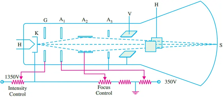
The anodes A1 and A3, which are both at positive potential with respect to K, operate to accelerate the electron beam (Fig. 2). The cylindrical focussing anode A2, being at negative potential, repels electrons from all sides and compresses them into a fine beam. The knob controlling the potential of A2 provides the focus control.
Deflecting Plates
Two sets of deflecting plates are used for deflecting the thin pencil-like electronic beam both in the vertical and horizontal directions. The first set marked Y (nearer to the gun) is for vertical deflection and X-set is for horizontal deflection.
When no potential is applied across the plates, beam passes between both sets of plates un-deflected and produces a bright spot at the centre of the screen.
If upper Y -plate is given a positive potential, the beam is deflected upwards depending on the value of the applied potential. Similarly, the beam (and hence the spot) deflects downwards when lower Y -plate is made positive.
However, if an alternating voltage is applied across the Y -plates, the spot keeps moving up and down thereby producing a vertical luminous trace on the screen due to persistence of vision. The maximum displacement of the spot from its central position is equal to the amplitude of the applied voltage.
The screen spot is deflected horizontally if similar voltages are applied to the X-plates. The dc potentials on the Y -and X-plates are adjustable by means of centering controls. It must be remembered that the signal to be displayed on the screen is always applied across the Y -plates.
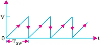
The voltage applied across X-plates is a ramp voltage i.e. a voltage which increases linearly with time. It has a sawtooth wave-form as shown in Fig. 3. It is also called horizontal time-base or sweep voltage. It has a sweep time of Tsw.
Glass Envelope
It is funnel-shaped having a phosphor-coated screen at its flared end. It is highly-evacuated in order to permit the electron beam to traverse the tube easily. The inside of the flared part of the tube is coated with a conducting graphite layer called Aquadag which is maintained at the same potential as A3. This layer performs two functions
- it accelerates the electron beam after it passes between the deflecting plates and
- collects the electrons produces by secondary emission when electron beam strikes the screen. Hence, it prevents the formation of negative charge on the screen.
The screen itself is coated with a thin layer of a flourescent material called phosphor. When struck by high-energy electrons, it glows.
In other words, it absorbs the kinetic energy of the electrons and converts it into light-the process being known as flourescence. That is why the screen is called flourescent screen. The colour of the emitted light depends on the type of phosphor used.
Deflection Sensitivity of a CRT
Fig. 4 shows the upward deflection of an electron beam when it passes between the vertical or Y -plates of a CRT. The beam deflects upwards because the upper Y -plate has been made positive with respect to the lower plate. Reversing the polarity of the applied voltage would, obviously, cause the beam to deflect downwards.
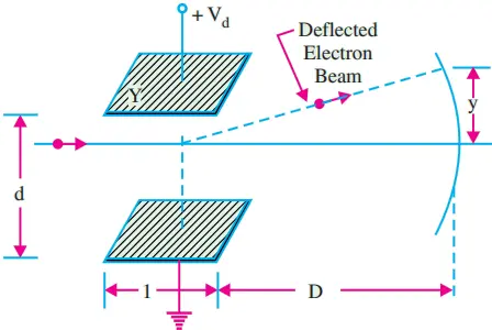
The vertical deflection of the beam
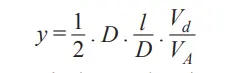
Where VA is the accelerating voltage applied to the electrons which make up the electron beam. The deflection sensitivity of a CRT is defined as the vertical deflection of the beam on the screen per unit deflecting voltage.