Overvoltage Protection by Lightning Arresters
There are two sources of overvoltages in the power system:
- external overvoltages due to mainly lightning, and
- internal overvoltages mainly due to switching operation.
The system can be protected against external overvoltages using what are known as shielding methods which do not allow an arc path to form between the line conductors and ground, thereby giving inherent protection in the line design.
For protection against internal voltages normally non-shielding methods are used which allow an arc path between the ground structure and the line conductor but means are provided to quench the arc.
The use of ground wire is a shielding method whereas the use of spark gaps, and lightning arresters are the non-shielding methods. However, the non-shielding methods can also be used for external overvoltages.
The non-shielding methods are based upon the principle of insulation breakdown as the overvoltage is incident on the protective device; thereby a part of the energy content in the overvoltage is discharged to the ground through the protective device.
The insulation breakdown is not only a function of voltage but it depends upon the time for which it is applied and also it depends upon the shape and size of the electrodes used.
The steeper the shape of the voltage wave, the larger will be the magnitude of voltage required for breakdown; this is because an expenditure of energy is required for the rupture of any dielectric, whether gaseous, liquid, or solid, and energy involves time.
The energy criterion for various insulations can be compared in terms of a common term known as Impulse Ratio which is defined as the ratio of breakdown voltage due to an impulse of specified shape to the breakdown voltage at power frequency.
The impulse ratio for a sphere gap is unity because this gap has a fairly uniform field and the breakdown takes place on the field ionization phenomenon mainly whereas for a needle gap it varies between 1.5 to 2.3 depending upon the frequency and gap length.
This ratio is higher than unity because of the non-uniform field between the electrodes. The impulse ratio of a gap of given geometry and dimension is greater with solid than with air dielectric.
The insulators should have a high impulse ratio for an economic design whereas the lightning arresters should have a low impulse ratio so that a surge incident on the lightning arrester may be bypassed to the ground instead of passing it on to the apparatus. The volt-time characteristics of gaps having one electrode grounded depend upon the polarity of the voltage wave.
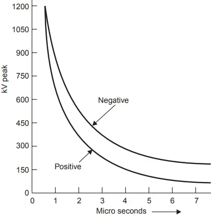
From Fig. 1 it is seen that the volt-time characteristic for positive polarity is lower than the negative polarity, i.e. the breakdown voltage for a negative impulse is greater than for a positive because of the nearness of earthed metal or of current-carrying conductors. For post insulators, the negative polarity wave has a high breakdown value whereas for suspension insulators the reverse is true.
Horn Gap
The horn gap consists of two horn-shaped rods separated by a small distance. One end of this is connected to be line and the other to the earth as shown in Fig. 2, with or without a series resistance. The choke connected between the equipment to be protected and the horn gap serves two purposes:
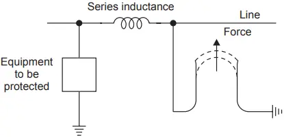
- The steepness of the wave incident on the equipment to be protected is reduced.
- It reflects the voltage surge back onto the horn.
Whenever a surge voltage exceeds the breakdown value of the gap a discharge takes place and the energy content in the rest part of the wave is by-passed to the ground. An arc is set up between the gap, which acts like a flexible conductor and rises upwards under the influence of the electromagnetic forces, thus increasing the length of the arc which eventually blows out.
There are two major drawbacks of the horn gap;
- The time of operation of the gap is quite large as compared to the modern protective gear.
- If used on isolated neutral the horn gap may constitute a vicious kind of arcing ground.
For these reasons, the horn gap has almost vanished from important power lines.
Surge Diverters
The following are the basic requirements of a surge diverter:
- It should not pass any current at normal or abnormal (normally 5% more than the normal voltage) power frequency voltage.
- It should break down as quickly as possible after the abnormally high-frequency voltage arrives.
- It should not only protect the equipment for which it is used but should discharge the surge current without damaging itself.
- It should interrupt the power frequency current after the surge is discharged to the ground.
There are mainly three types of surge diverters:
(i) Rod gap, (ii) Protector tube or expulsion type of lightning arrester, (iii) Valve type of lightning arrester.
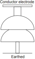
Rod gap: This type of surge diverter is perhaps the simplest, cheapest, and most rugged one. Fig. 3 shows one such gap for a breaker bushing. This may take the form of an arcing ring. Fig. 4 shows the breakdown characteristics (volt-time) of a rod gap. For a given gap and wave shape of the voltage, the time for breakdown varies approximately inversely with the applied voltage.
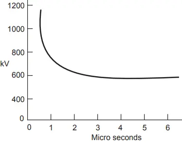
The time to flashover for positive polarity is lower than for negative polarities. Also, it is found that the flashover voltage depends to some extent on the length of the lower (grounded) rod. For low values of this length, there is a reasonable difference between positive (lower value) and negative flashover voltages.
Usually a length of 1.5 to 2.0 times the gap spacing is good enough to reduce this difference to a reasonable amount. The gap setting normally chosen is such that its breakdown voltage is not less than 30% below the voltage withstand level of the equipment to be protected.
Even though rod gap is the cheapest form of protection, it suffers from a major disadvantage that it does not interrupt the power frequency follow current. This means that every operation of the rod gap results in a L-G fault and the breakers must operate to de-energize the circuit to clear the flashover. The rod gap, therefore, is generally used as backup protection.
Expulsion type of lightning arrester: An improvement of the rod gap is the expulsion tube which consists of
- a series gap external to the tube which is good enough to withstand normal system voltage, thereby there is no possibility of corona or leakage current across the tube;
- a tube which has a fiber lining on the inner side which is a highly gas evolving material;
- a spark gap in the tube; and
- an open vent at the lower end for the gases to be expelled (Fig. 5).
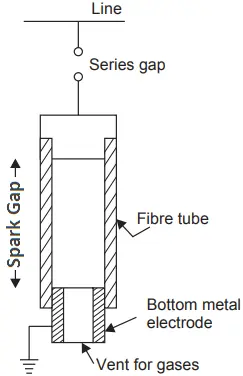
It is desired that the breakdown voltage of a tube must be lower than that of the insulation for which it is used. When a surge voltage is incident on the expulsion tube the series gap is spanned and an arc is formed between the electrodes within the tube. The heat of the arc vaporizes some of the organic material of the tube wall causing a high gas pressure to build up in the tube.
The resulting neutral gas creates a lot of turbulence within the tube and is expelled out from the open bottom vent of the tube and it extinguishes the arc at the first current zero. At this instant, the rate of build-up of insulation strength is greater than the RRRV. Very high currents have been interrupted using these tubes.
The breakdown voltage of expulsion tubes is slightly lower than for plain rod gaps for the same spacing. With each operation of the tube, the diameter of the tube (fiber lining) increases; thereby the insulation characteristics of the tube will lower down even though not materially. The volt-time characteristics (Fig. 6) of the expulsion tube are somewhat better than the rod gap and have the ability to interrupt power voltage after flashover.
Valve-type lightning arresters: An improved but more expensive surge diverter is the valve-type lightning arrester or a non-linear surge diverter. A porcelain bushing contains several series gaps, coil units, and the valve elements of the non-linear resistance material usually made of silicon carbide disc, the latter possessing low resistance to high currents and high resistance to low currents.
The characteristic is usually expressed as I = KVn; where n lies between 2 and 6 and K is constant, a function of the geometry and dimension of the resistor.
The non-linear characteristic is attributed to the properties of the electrical contacts between the grains of silicon carbide. The discs are 90 mm in diameter and 25 mm thick. A grading ring or a high resistance is connected across the disc so that the system voltage is evenly distributed over the discs. The high resistance keeps the inner assembly dry due to some heat generated.
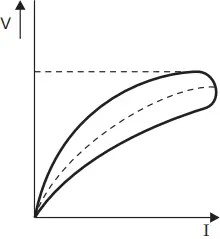
Figure 7 shows the volt-ampere characteristics of a non-linear resistance of the required type. The closed curve represents the dynamic characteristic corresponding to the application of a voltage surge whereas the dotted line represents the static characteristic. The voltage corresponding to the horizontal tangent to the dynamic characteristic is known as the residual voltage (IR drop) and is the peak value of the voltage during the discharge of the surge current.
This voltage varies from 3 kV to 6 kV depending upon the type of arrester i.e., whether station or line type, the magnitude and wave shape of the discharge current.
The spark gaps are so designed that they give an impulse ratio of unity to the surge diverter and as a result, they are unable to interrupt high values of current, and the follow-up currents are limited to 20 to 30 A.
The impulse breakdown strength of a diverter is smaller than the residual voltage, and therefore, from the point of view of insulation coordination residual voltage decides the protection level.
The operation of the arrester can be easily understood with the help of Fig 8. When a surge voltage is incident at the terminal of the arrester it causes the two gap units to flashover, thereby a path is provided to the surge to the ground through the coil element and the non-linear resistor element.
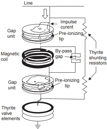
Because of the high frequency of the surge, the coil develops sufficient voltage across its terminals to cause the by-pass gap to flashover. With this, the coil is removed from the circuit and the voltage across the LA is the IR drop due to the non-linear element.
This condition continues till power frequency currents follow the preionized path. For power frequency the impedance of the coil is very low and, therefore, the arc will become unstable and the current will be transferred to the coil.
The magnetic field developed by the follow current in the coil reacts with this current in the arcs of the gap assemblies, causing them to be driven into arc-quenching chambers which are an integral part of the gap unit.
The arc is extinguished at the first current zero by cooling and lengthening the arc and also because the current and voltage are almost in phase. Thus the diverter comes back to a normal state after discharging the surge to the ground successfully.
Location of Lightning Arresters
The normal practice is to locate the lightning arrester as close as possible to the equipment to be protected. The following are the reasons for the practice:
- This reduces the chances of surges entering the circuit between the protective equipment and the equipment to be protected.
- If there is a distance between the two, a steep fronted wave after being incident on the lightning arrester, which sparks over corresponding to its spark over voltage, enters the transformer after traveling over the lead between the two. The wave suffers reflection at the terminal and, therefore, the total voltage at the terminal of the transformer is the sum of reflected and the incident voltage which approaches nearly twice the incident voltage i.e., the transformer may experience a surge twice as high as that of the lightning arrester. If the lightning arrester is right at the terminals this could not occur.
- If L is the inductance of the lead between the two, and IR the residual voltage of the lightning arrester, the voltage incident at the transformer terminal will be V = IR + L di/dt; where di/dt is the rate of change of the surge current. It is possible to provide some separation between the two, where a capacitor is connected at the terminals of the equipment to be protected. This reduces the steepness of the wave and hence the rate di/dt and this also reduces the stress distribution over the winding of the equipment.
There are three classes of lightning arresters available:
- Station type: The voltage ratings of such arresters vary from 3 kV to 312 kV and are designed to discharge currents not less than 100,000 amps. They are used for the protection of substations and power transformers.
- Line type: The voltage ratings vary from 20 kV to 73 kV and can discharge currents between 65,000 amps and 100,000 amps. They are used for the protection of distribution transformers, small power transformers, and sometimes small substations.
- Distribution type: The voltage ratings vary from 8 kV to 15 kV and can discharge currents up to 65,000 amperes. They are used mainly for pole-mounted substations for the protection of distribution transformers up to and including the 15 kV classification.
Rating of Lightning Arrester
A lightning arrester is expected to discharge surge currents of very large magnitude, thousands of amperes, but since the time is very short in terms of microseconds, the energy that is dissipated through the lightning arrester is small compared with what it would have been if a few amperes of power frequency current had been flown for a few cycles.
Therefore, the main consideration in selecting the rating of a lightning arrester is the line-to-ground dynamic voltage to which the arrester may be subjected for any condition of system operation. An allowance of 5% is normally assumed, to take into account the light operating condition under no load at the far end of the line due to the Ferranti effect and the sudden loss of load on water wheel generators.
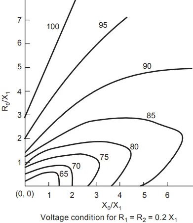
This means an arrester of 105% is used on a system where the line-to-ground voltage may reach line-to-line value during line-to-ground fault conditions. The overvoltages on a system as discussed earlier depend upon the neutral grounding condition which is determined by the parameters of the system. We recall that a system is said to be solidly grounded only if
Ro/X1 ≤ 1 and
Xo/X1 ≤ 3 and under this condition the line-to-ground voltage during an L-G fault does not exceed 80% of the L-L voltage and, therefore, an arrester of (80% + 0.05 × 80%) = 1.05 × 80% = 84% is required.
This is the extreme situation in the case of a solidly grounded system. In the same system the voltage may be less than 80%; say it may be 75%. In that case, the rating of the lightning arrester will be 1.05 × 75% = 78.75%.
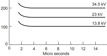
The overvoltages can be obtained with the help of pre-calculated curves. One set of curves corresponding to a particular system is given in Fig. 9.
For a system grounded through Peterson coil, the overvoltages may be 100% if it is properly tuned, and, therefore, it is customary to apply an arrester of 105% for such systems.
Even though there is a risk of overvoltage becoming more than 100% if it is not properly tuned, it is generally not feasible to select arresters of sufficiently high rating to eliminate all risks of arrester damage due to these reasons. The voltage rating of the arrester, therefore, ranges between 75% to 105% depending upon the neutral grounding condition.
Related Posts
- Lightning Arrester Types & Working
- Lightning and Switching Voltage Protection Methods
- Personnel Protective Devices
- How Lightning Arrester Works
- Overvoltage Protection by Lightning Arresters
- Insulation coordination of Electrical Equipment
- MCCB Circuit Breakers
- Differential Protection of Generator & Alternator
- Types of Current Limiting Reactor
- Classification | Types of Protective Relays
- Fuse Selection Criteria
- Protection of Transmission lines by Ground Wires