Cathode Ray Oscilloscope – CRO
It is generally referred to as oscilloscope or scope and is the basic tool of an electronic engineer and technician as voltmeter, ammeter and wattmeter are those of an electrical engineer or electrician.
The CRO provides a two-dimensional visual display of the signal wave-shape on a screen thereby allowing an electronic engineer to ‘see’ the signal in various parts of the circuit.
It, in effect, gives the electronic engineer an eye to ‘see’ what is happening inside the circuit itself. It is only by ‘seeing’ the signal waveforms that he/she can correct errors, understand mistakes in the circuit design and thus make suitable adjustments.
An oscilloscope can display and also measure many electrical quantities like ac/dc voltage, time, phase relationships, frequency and a wide range of waveform characteristics like rise-time, fall-time and overshoot etc.
Non-electrical quantities like pressure, strain, temperature and acceleration etc. can also be measured by using different transducers to first convert them into an equivalent voltage.
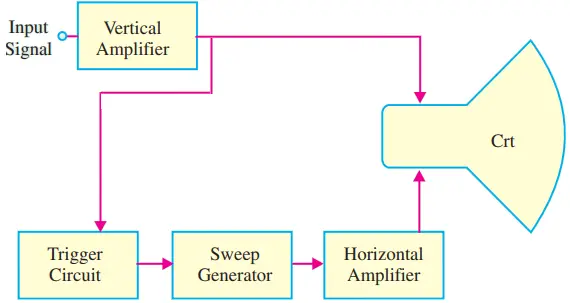
As seen from the block diagram of an oscilloscope (Fig. 1), it consists of the following major sub-systems:-
- Cathode Ray Tube (CRT) – it displays the quantity being measured.
- Vertical amplifier – it amplifies the signal waveform to be viewed.
- Horizontal amplifier – it is fed with a sawtooth voltage which is then applied to the X-plates.
- Sweep generator – produces sawtooth voltage waveform used for horizontal deflection of the electron beam.
- Trigger circuit – produces trigger pulses to start horizontal sweep.
- High and low-voltage power supply (not shown in Fig. for simplicity).
The operating controls of a basic oscilloscope are shown in Fig. 2.
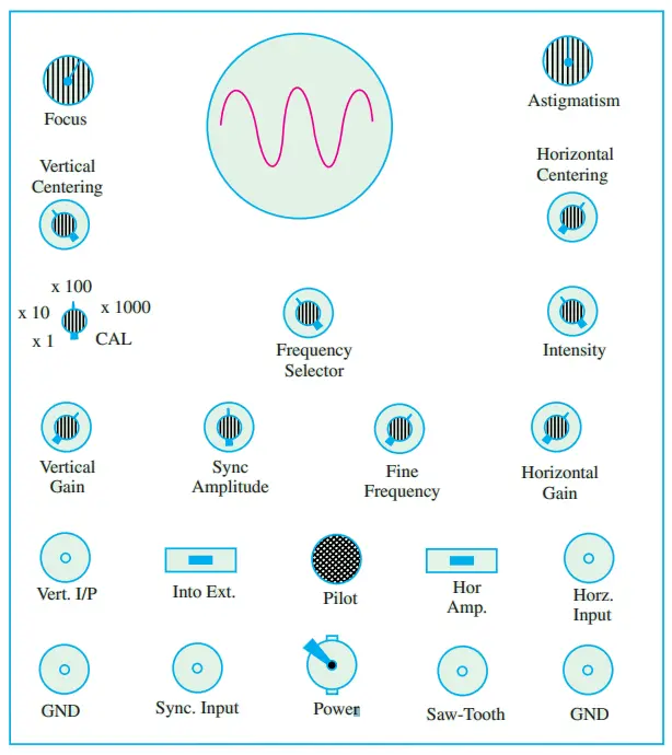
The different terminals provide. 1. horizontal amplifier input, 2. vertical amplifier input, 3. sync. input, 4. Z-axis input, 5. external sweep input.
As seen, different controls permit adjustment of
- Intensity – for correct brightness of the trace on the screen,
- Focus – for sharp focus of the trace.
- Horizontal centering – for moving the pattern right and left on the screen.
- Vertical centering – for moving the pattern up and down on the screen.
- Horizontal gain (also Time/div or Time/cm) – for adjusting pattern width.
- Vertical gain (also volt/div or volt/cm)–for adjusting pattern height.
- Sweep frequency – for selecting number of cycles in the pattern.
- Sync. voltage amplitude – for locking the pattern.
The different switches permit selection of: 1. sweep type, 2. sweep range, 3. sync. Type
A CRO can operate upto 500 MHz, can allow viewing of signals within a time span of a few nanoseconds and can provide a number of waveform displays simultaneously on the screen. It also has the ability to hold the displays for a short or long time (of many hours) so that the original signal may be compared with one coming on later.
Normal Operation of a CRO
The signal to be viewed or displayed on the screen is applied across the Y -plates of a CRT. But to see its waveform or pattern, it is essential to spread it out horizontally from left to right. It is achieved by applying a sawtooth voltage wave (produced by a time base generator) to X-plates.
Under these conditions, the electron beam would move uniformly from left to right thereby graphic vertical variations of the input signal versus time. Due to repetitive tracing of the viewed waveform, we get a continuous display because of persistence of vision.
However, for getting a stable stationary display on the screen, it is essential to synchronize the horizontal sweeping of the beam (sync) with the input signal across Y -plates. The signal will be properly synced only when its frequency equals the sweep-generator frequency.
In general, for proper synchronization of time-base with the signal, the condition is
Tsw = n Ts
Where Ts the time-period of the signal and n is an integer. If n = 1, then Tsw = Ts i.e. time-periods of the sweep voltage and input signal voltage are equal, then one cycle of the signal would be displayed as shown in Fig. 3 (a).
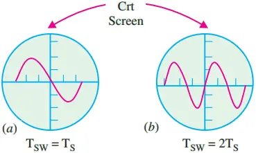
On the other hand, if Tsw is twice Ts, then two cycles of the signal voltage would be displayed as shown in Fig. 3 (b). Obviously, three full cycles of the input voltage would be spread out on the screen when Tsw = 3 Ts
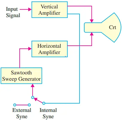
Internal Synchronization: The periodic sawtooth voltage which is applied to X-plates for horizontal sweep (or scan) of the beam across the screen is usually provided by the unijunction relaxation oscillator.
When the sawtooth voltage falls abruptly to zero, the beam experience no horizontal deflection and hence flies back almost instantly to the original (central) position. The usual method of synchronizing the input signal is to use a portion of the input signal to trigger the sweep generator so that the frequency of the sweep signal is locked or synchronized to the input signal. It is called internal sync. because the synchronization is obtained by internal wiring connection as shown in the block the diagram of Fig. 4.
Triggered and Non-Triggered Oscilloscopes
Oscilloscopes may be classified into two basic types:-
- Triggered sweep type.
- Recurrent sweep (free-running) type.
Triggered oscilloscopes, being more sophisticated, are generally used in industrial laboratories and plants, in engineering and technical school laboratories and in all those applications which require study of low- and high-frequency waveforms, for accurate measurement of time and timing relationships etc.
A non-triggered oscilloscope is generally used in servicing work where a certain amount of waveform error can be tolerated and bandwidth requirements are limited to a few MHz. The sweep (or ramp) generator which produces sawtooth voltage for X-deflection plates is prresent in both types of scopes.
In non-triggered oscilloscopes, this generator runs continuously (recurrent sweep) and the control and calibration of the sweep is based on the repetition frequency of the sweep.
For producing a stable stationary display, the sweep frequency has to be forced into synchronization with the input signal on the Y -plates. This is done by manually adjusting the free-running sweep frequency to a value very close to signal frequency (or some submultiple of it) and then depending on the internal sync signal (derived from the input) for locking the sweep generator into exact step.
Unfortunately, this method is limited to the display of signals which have constant frequency and amplitude. Hence voice or music signals from a microphone cannot be displayed on this scope because it has to be readjusted for each for new change in frequency. Moreover, a free-running or recurrent time base cannot display less than one complete cycle of the input signal on the scope screen.
On the other hand, triggered time base can be adjusted to pick out a small part of a waveform which can then be expended horizontally for evaluation of waveform details.
The triggered oscilloscope is provided with a triggered (or driven) sweep. Here the input signal is caused to generate pulses that trigger the sweep thereby ensuring that the sweep is necessarily in step with the trigger that drives it.
Hence, screen display remains stable in spite of variations in the frequency or amplitude of the input signal. It means that there is automatic mode of triggering in such scopes. Consequently, input signals of very short duration can be displayed for the simple reason that sweep is initiated by a trigger pulse derived from the waveform under observation.
Dual Trace CRO
Such oscilloscopes are used extensively by industrial firms and research laboratories. They produce a dual-trace display by means of electronic switching of two separate input signals. As shown in the block diagram of Fig. 5, there are two vertical input circuits marked channel A and B with identical pre-amplifiers.
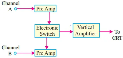
The outputs of these preamplifiers are fed to an electronic switch which alternately connects them to the main vertical amplifier of the oscilloscope.
In this type of scope, there is only one electron beam. The electron switch is also capable of selecting a variety of display modes.
Dual Beam CRO
Such a CRO has two sets of vertical deflection plates and has two electronic beams which produce two separate traces on the scope screen by using the same set of horizontal deflection plates.
This scope makes it possible to observe two time-related wave forms at different points i.e. the electronic circuit. Such a scope does not have the same number of display modes as the dual-trace scope yet it is ideally suited for different input signals.
Storage Oscilloscope
It can retain a CRT display for 10 to 150 hours after the pattern is first produced on the screen. It uses the phenomenon of secondary electron emission to build up and store electrostatic charges on the surface of an insulated target. Such oscilloscopes are especially useful.
- For real-time observation of events that occur only once.
- For displaying the waveform of a very low-frequency signal.
It has a disk drive which makes the saving of screen images or data to a disk. The disk can then be inserted into your personal computer (PC) for importing to desk top publishing or spreadsheet programs.
The storage oscilloscopes find their application in biophysics/biomedical research, audio system measurement and analysis, power supply and power-related design, electro-physical and electromechanical system design etc.
Sampling CRO
It is specifically meant to observe very high frequency repetitive electric signals by using the sampling technique. Such high-frequency signals cannot be viewed by conventional oscilloscopes because its frequency range is limited by the gain-bandwidth product of its vertical amplifier. The sampling technique ‘slows down’ the signal frequency many thousands of times thereby making it easier to view it on the screen.
Digital Readout CRO
It provides digital readout of the signal information such as voltage or time etc. in addition to the conventional CRT display. It consists of a high-speed laboratory CRO and an electronic counter, both contained in one cabinet.
Handheld Battery Operated Oscilloscope
This type of an oscilloscope is extremely useful for electric/power electronics measurements. Examples of such measurements are:-
- testing and verifying correct operation of motors
- checking transformer efficiency,
- verifying power supply performance,
- measuring the effect of neutral current etc.
Applications of a CRO
As stated earlier, no other instrument in electronic industry is as versatile as a CRO. In fact, a modern oscilloscope is the most useful single piece of electronic equipment that not only removes guess work from technical troubleshooting but makes it possible to determine the trouble quickly. Some of its uses are as under:-
(a) In Radio Work
- To trace and measure a signal throughout the RF, IF and AF channels of radio and television receivers.
- It provides the only effective way of adjusting FM receivers, broadband high-frequency RF amplifiers and automatic frequency control circuits;
- To test AF circuits for different types of distortions and other spurious oscillations;
- To give visual display of waveshapes such as sine waves, square waves and their many different combinations;
- To trace transistor curves
- To visually show the composite synchronized TV signal
- To display the response of tuned circuits etc.
(b) Scientific and Engineering Applications
- measurement of ac/dc voltages,
- finding B/H curves for hysteresis loop,
- for engine pressure analysis,
- for study of stress, strain, torque, acceleration etc.,
- frequency and phase determination by using Lissajous figures,
- radiation patterns of antenna,
- amplifier gain,
- modulation percentage,
- complex waveform as a short-cut for Fourier analysis,
- standing waves in transmission lines etc.
Oscilloscope Specifications and Performance
The oscilloscope specifications are necessary when choosing a particular oscilloscope for a particular application. It is necessary to look in detail at the specifications list to see whether the instrument meets its requirements. The oscilloscope specifications and performance are given below:
1. Bandwidth: The bandwidth specification tells you the frequency range the oscilloscope accurately measures. As signal frequency increases, the capability of the oscilloscope to accurately respond decreases. By convention, the bandwidth tells you the frequency at which the displayed signal reduces to 70.7% of the applied sine wave signal. (This 70.7% point is referred to as the “–3 dB point,” a term based on a logarithmic scale.)
2. Rise Time: Rise time is another way of describing the useful frequency range of an oscilloscope. Rise time may be a more appropriate performance consideration when you expect to measure pulses and steps. An oscilloscope cannot accurately display pulses with rise times faster than the specified rise time of the oscilloscope.
3. Vertical Sensitivity: The vertical sensitivity indicates how much the vertical amplifier can amplify a weak signal. Vertical sensitivity is usually given in millivolts (mV) per division. The smallest voltage a general purpose oscilloscope can detect is typically about 2 mV per vertical screen division.
4. Sweep Speed: For analog oscilloscopes, this specification indicates how fast the trace can sweep across the screen, allowing you to see fine details. The fastest sweep speed of an oscilloscope is usually given in nanoseconds/div.
5. Gain Accuracy: The gain accuracy indicates how accurately the vertical system attenuates or amplifies a signal. This is usually listed as a percentage error.
6. Time Base or Horizontal Accuracy: The time base or horizontal accuracy indicates how accurately the horizontal system displays the timing of a signal. This is usually listed as a percentage error.
7. Sample Rate: On digital oscilloscopes, the sampling rate indicates how many samples per second the ADC (and therefore the oscilloscope) can acquire. Maximum sample rates are usually given in mega-samples per second (MS/s).
The faster the oscilloscope can sample, the more accurately it can represent fine details in a fast signal. The minimum sample rate may also be important if you need to look at slowly changing signals over long periods of time.
Typically, the sample rate changes with changes made to the sec/div control to maintain a constant number of waveform points in the waveform record.
8. ADC Resolution (Or Vertical Resolution): The resolution, in bits, of the ADC (and therefore the digital oscilloscope) indicates how precisely it can turn input voltages into digital values. Calculation techniques can improve the effective resolution.
9. Record Length: The record length of a digital oscilloscope indicates how many waveform points the oscilloscope is able to acquire for one waveform record. Some digital oscilloscopes let you adjust the record length. The maximum record length depends on the amount of memory in your oscilloscope.
Since the oscilloscope can only store a finite number of waveform points, there is a trade-off between record detail and record length. You can acquire either a detailed picture of a signal for a short period of time (the oscilloscope “fills up” on waveform points quickly) or a less detailed picture for a longer period of time.
Some oscilloscopes let you add more memory to increase the record length for special application.