Protection of Transmission Lines
The probability of faults occurring on the lines is much more due to their greater length and exposure to atmospheric conditions. This has called for many protective schemes which have no application to the comparatively simple cases of alternators and transformers. The requirements of line protection are:-
- In the event of a short-circuit, the circuit breaker closest to the fault should open, all other circuit breakers remaining in a closed position.
- In case the nearest breaker to the fault fails to open, back-up protection should be provided by the adjacent circuit breakers.
- The relay operating time should be just as short as possible in order to preserve system stability, without unnecessary tripping of circuits.
The protection of lines presents a problem quite different from the protection of station apparatus such as generators, transformers and busbars. While differential protection is ideal method for lines, it is much more expensive to use. The two ends of a line may be several kilometres apart and to compare the two currents, a costly pilot-wire circuit is required. This expense may be justified but in general less costly methods are used. The common methods of line protection are:-
- Time-graded overcurrent protection
- Differential protection
- Distance protection
Time Graded Overcurrent Protection
In this scheme of overcurrent protection, time discrimination is incorporated. In other words, the time setting of relays is so graded that in the event of fault, the smallest possible part of the system is isolated. We shall discuss a few important cases.
1. Radial feeder. The main characteristic of a radial system is that power can flow only in one direction, from generator or supply end to the load. It has the disadvantage that continuity of supply cannot be maintained at the receiving end in the event of fault. Time-graded protection of a radial feeder can be achieved by using
- definite time relays and
- inverse time relays.
(i) Using definite time relays. Fig. 1 shows the overcurrent protection of a radial feeder by definite time relays. The time of operation of each relay is fixed and is independent of the operating current. Thus relay D has an operating time of 0·5 second while for other relays, time delay is successively increased by 0·5 second.
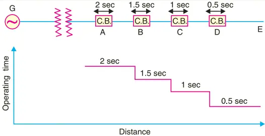
If a fault occurs in the section DE, it will be cleared in 0·5 second by the relay and circuit breaker at D because all other relays have higher operating time. In this way only section DE of the system will be isolated.
If the relay at D fails to trip, the relay at C will operate after a time delay of 0·5 second i.e. after 1 second from the occurrence of fault.
The disadvantage of this system is that if there are a number of feeders in series, the tripping time for faults near the supply end becomes high (2 seconds in this case). However, in most cases, it is necessary to limit the maximum tripping time to 2 seconds.
This disadvantage can be overcome to a reasonable extent by using inverse-time relays.
(ii) Using inverse time relays. Fig. 2 shows overcurrent protection of a radial feeder using inverse time relays in which operating time is inversely proportional to the operating current. With this arrangement, the farther the circuit breaker from the generating station, the shorter is its relay operating time.
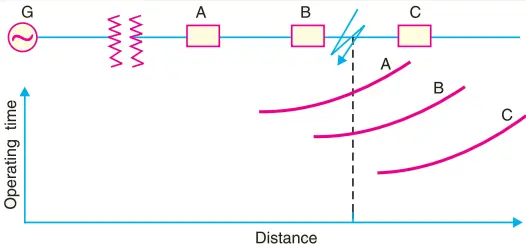
The three relays at A, B and C are assumed to have inverse-time characteristics. A fault in section BC will give relay times which will allow breaker at B to trip out before the breaker at A.
2. Parallel feeders. Where continuity of supply is particularly necessary, two parallel feeders may be installed. If a fault occurs on one feeder, it can be disconnected from the system and continuity of supply can be maintained from the other feeder.
The parallel feeders cannot be protected by non-directional overcurrent relays only. It is necessary to use directional relays also and to grade the time setting of relays for selective trippings.
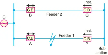
Fig. 3 shows the system where two feeders are connected in parallel between the generating station and the sub-station. The protection of this system requires that
- each feeder has a non-directional overcurrent relay at the generator end. These relays should have inverse-time characteristic.
- each feeder has a reverse power or directional relay at the sub-station end. These relays should be instantaneous type and operate only when power flows in the reverse direction i.e. in the direction of arrow at P and Q.
Suppose an earth fault occurs on feeder 1 as shown in Fig. 3. It is desired that only circuit breakers at A and P should open to clear the fault whereas feeder 2 should remain intact to maintain the continuity of supply. In fact, the above arrangement accomplishes this job.
The shown fault is fed via two routes, viz.
- directly from feeder 1 via the relay A
- from feeder 2 via B, Q, sub-station and P
Therefore, power flow in relay Q will be in normal direction but is reversed in the relay P. This causes the opening of circuit breaker at P. Also the relay A will operate while relay B remains inoperative.
It is because these relays have inverse-time characteristics and current flowing in relay A is in excess of that flowing in relay B. In this way only the faulty feeder is isolated.
3. Ring main system. In this system, various power stations or sub-stations are interconnected by alternate routes, thus forming a closed ring. In case of damage to any section of the ring, that section may be disconnected for repairs, and power will be supplied from both ends of the ring, thereby maintaining continuity of supply.
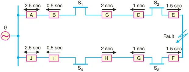
Fig. 4 shows the single line diagram of a typical ring main system consisting of one generator G supplying four sub-stations S1, S2, S3 and S4. In this arrangement, power can flow in both directions under fault conditions. Therefore, it is necessary to grade in both directions round the ring and also to use directional relays.
In order that only faulty section of the ring is isolated under fault conditions, the types of relays and their time settings should be as follows:-
- The two lines leaving the generating station should be equipped with non-directional overcurrent relays (relays at A and J in this case).
- At each sub-station, reverse power or directional relays should be placed in both incoming and outgoing lines (relays at B, C, D, E, F, G, H and I in this case).
- There should be proper relative time-setting of the relays. As an example, going round the loop G S1 S2 S3 S4 G; the outgoing relays (viz at A, C, E, G and I) are set with decreasing time limits e.g.
A = 2·5 sec, C = 2 sec, E = 1·5 sec G = 1 sec and I = 0·5 sec
Similarly, going round the loop in the opposite direction (i.e. along G S4 S3 S2 S1 G), the outgoing relays (J, H, F, D and B) are also set with a decreasing time limit e.g.
J = 2·5 sec, H = 2 sec, F = 1·5 sec, D = 1 sec, B = 0·5 sec.
Suppose a short circuit occurs at the point as shown in Fig. 4. In order to ensure selectivity, it is desired that only circuit breakers at E and F should open to clear the fault whereas other sections of the ring should be intact to maintain continuity of supply.
In fact, the above arrangement accomplishes this job. The power will be fed to the fault via two routes viz.
- from G around S1 and S2 and
- from G around S4 and S3.
It is clear that relays at A, B, C and D as well as J, I, H and G will not trip. Therefore, only relays at E and F will operate before any other relay operates because of their lower time-setting.
Differential Pilot Wire Protection of Transmission Lines
The differential pilot-wire protection is based on the principle that under normal conditions, the current entering one end of a line is equal to that leaving the other end.
As soon as a fault occurs between the two ends, this condition no longer holds and the difference of incoming and outgoing currents is arranged to flow through a relay which operates the circuit breaker to isolate the faulty line.
There are several differential protection schemes in use for the lines. However, only the following two schemes will be discussed:-
- Merz-Price voltage balance system
- Translay scheme
1. Merz-Price voltage balance system. Fig. 5 shows the single line diagram of Merz-Price voltage balance system for the protection of a 3-phase line. Identical current transformers are placed in each phase at both ends of the line.
The pair of CTs in each line is connected in series with a relay in such a way that under normal conditions, their secondary voltages are equal and in opposition i.e. they balance each other.
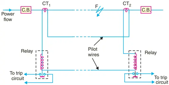
Under healthy conditions, current entering the line at one-end is equal to that leaving it at the other end. Therefore, equal and opposite voltages are induced in the secondaries of the CTs at the two ends of the line. The result is that no current flows through the relays.
Suppose a fault occurs at point F on the line as shown in Fig. 5. This will cause a greater current to flow through CT1 than through CT2.
Consequently, their secondary voltages become unequal and circulating current flows through the pilot wires and relays. The circuit breakers at both ends of the line will trip out and the faulty line will be isolated.
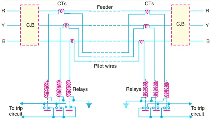
Fig. 6 shows the connections of Merz-Price voltage balance scheme for all the three phases of the line.
Advantages
- This system can be used for ring mains as well as parallel feeders.
- This system provides instantaneous protection for ground faults. This decreases the possibility of these faults involving other phases.
- This system provides instantaneous relaying which reduces the amount of damage to overhead conductors resulting from arcing faults.
Disadvantages
- Accurate matching of current transformers is very essential.
- If there is a break in the pilot-wire circuit, the system will not operate.
- This system is very expensive owing to the greater length of pilot wires required.
- In case of long lines, charging current due to pilot-wire capacitance effects may be sufficient to cause relay operation even under normal conditions.
- This system cannot be used for line voltages beyond 33 kV because of constructional difficulties in matching the current transformers.
2. Translay scheme. This system is similar to voltage balance system except that here balance or opposition is between the voltages induced in the secondary windings wound on the relay magnets and not between the secondary voltages of the line current transformers.
This permits to use current transformers of normal design and eliminates one of the most serious limitations of original voltage balance system, namely ; its limitation to the system operating at voltages not exceeding 33 kV.
The application of Translay scheme for a single phase line has already been discussed in a previous article. This can be extended to 3-phase system by applying one relay at each end of each phase of the 3-phase line.
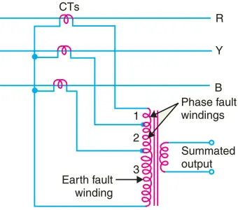
However, it is possible to make further simplification by combining currents derived from all phases in a single relay at each end, using the principle of summation transformer (See Fig. 7). A summation transformer is a device that reproduces the poly-phase line currents as a single-phase quantity.
The three lines CTs are connected to the tapped primary of summation transformer. Each line CT energises a different number of turns (from line to neutral) with a resulting single phase output.
The use of summation transformer permits two advantages viz.
- primary windings 1 and 2 can be used for phase faults whereas winding 3 can be used for earth fault
- the number of pilot wires required is only two. Schematic arrangement.
The Translay scheme for the protection of a 3-phase line is shown in Fig. 8. The relays used in the scheme are essentially overcurrent induction type relays.
Each relay has two electromagnetic elements. The upper element carries a winding (11 or 11 a) which is energised as a summation transformer from the secondaries of the line CTs connected in the phases of the line to be protected.
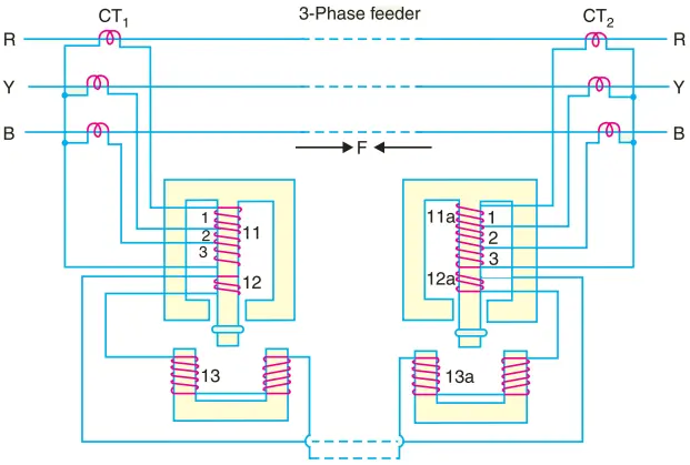
The upper element also carries a secondary winding (12 or 12 a) which is connected is series with the operating winding (13 or 13 a) on the lower magnet.
The secondary windings 12, 12 a and operating windings 13, 13 a are connected in series in such a way that voltages induced in them oppose each other.
Note that relay discs and tripping circuits have been omitted in the diagram for clarity.
Operation. When the feeder is sound, the currents at its two ends are equal so that the secondary currents in both sets of CTs are equal.
Consequently, the currents flowing in the relay primary winding 11 and 11 a will be equal and they will induce equal voltages in the secondary windings 12 and 12a. Since these windings are connected in opposition, no current flows in them or in the operating windings 13 and 13a.
In the event of a fault on the protected line, the line current at one end must carry a greater current than that at the other end. The result is that voltages induced in the secondary windings 12 and 12 a will be different and the current will flow through the operating coils 13, 13a and the pilot circuit.
Under these conditions, both upper and lower elements of each relay are energised and a forward torque acts on the each relay disc. The operation of the relays will open the circuit breakers at both ends of the line.
(i) Suppose a fault F occurs between phases R and Y and is fed from both sides as shown in Fig. 8.
This will energise only section 1 of primary windings 11 and 11a and induce voltages in the secondary windings 12 and 12a. As these voltages are now additive, therefore, current will circulate through operating coils 13, 13a and the pilot circuit.
This will cause the relay contacts to close and open the circuit breakers at both ends. A fault between phases Y and B energises section 2 of primary windings 11 and 11a whereas that between R and B will energise the sections 1 and 2.
(ii) Now imagine that an earth fault occurs on phase R. This will energise sections 1, 2 and 3 of the primary windings 11 and 11a. Again if fault is fed from both ends, the voltages induced in the secondary windings 12 and 12a are additive and cause a current to flow through the operating coils 13, 13a.
The relays, therefore, operate to open the circuit breakers at both ends of the line. In the event of earth fault on phase Y , sections 2 and 3 of primary winding 11 and 11a will be energised and cause the relays to operate. An earth fault on phase B will energise only section 3 of relay primary windings 11 and 11a.
Advantages
- The system is economical as only two pilot wires are required for the protection of a 3-phase line.
- Current transformers of normal design can be used.
- The pilot wire capacitance currents do not affect the operation of relays.
Distance Protection of Transmission Lines
Both time-graded and pilot-wire systems are not suitable for the protection of very long high voltage transmission lines.
The former gives an unduly long time delay in fault clearance at the generating station end when there are more than four or five sections and the pilot-wire system becomes too expensive owing to the greater length of pilot wires required.
This has led to the development of distance protection in which the action of relay depends upon the distance (or impedance) between the point where the relay is installed and the point of fault. This system provides discrimination protection without employing pilot wires.
The principle and operation of distance relays have already been discussed in a previous article. We shall now consider its application for the protection of transmission lines.
Fig. 9(i) shows a simple system consisting of lines in series such that power can flow only from left to right. The relays at A, B and C are set to operate for impedance less than Z1, Z2 and Z3 respectively.
Suppose a fault occurs between sub-stations B and C, the fault impedance at power station and sub-station A and B will be Z1 + Z and Z respectively. It is clear that for the portion shown, only relay at B will operate.
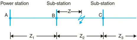
Similarly, if a fault occurs within section A B, then only relay at A will operate. In this manner, instantaneous protection can be obtained for all conditions of operation.
In actual practice, it is not possible to obtain instantaneous protection for complete length of the line due to inaccuracies in the relay elements and instrument transformers.
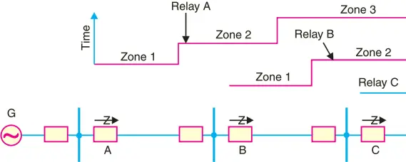
Thus the relay at A [See Fig. 9(i)] would not be very reliable in distinguishing between a fault at 99% of the distance A B and the one at 101% of distance A B. This difficulty is overcome by using ‘three-zone’ distance protection shown in Fig. 9(ii).
In this scheme of protection, three distance elements are used at each terminal.
- The zone 1 element covers first 90% of the line and is arranged to trip instantaneously for faults in this portion.
- The zone 2 element trips for faults in the remaining 10% of the line and for faults in the next line section, but a time delay is introduced to prevent the line from being tripped if the fault is in the next section.
- The zone 3 element provides back-up protection in the event a fault in the next section is not cleared by its breaker.