3-Phase Transformer Protection Schemes
Transformers are static devices, totally enclosed and generally oil immersed. Therefore, chances of faults occurring on them are very rare. However, the consequences of even a rare fault may be very serious unless the transformer is quickly disconnected from the system. This necessitates to provide adequate automatic protection for transformers against possible faults.
Small distribution transformers are usually connected to the supply system through series fuses instead of circuit breakers. Consequently, no automatic protective relay equipment is required. However, the probability of faults on power transformers is undoubtedly more and hence automatic protection is absolutely necessary.
Common transformer faults. As compared with generators, in which many abnormal conditions may arise, power transformers may suffer only from:-
(i) open circuits (ii) overheating (iii) winding short-circuits e.g. earth-faults, phase-to-phase faults and inter-turn faults.
An open circuit in one phase of a 3-phase transformer may cause undesirable heating. In practice, relay protection is not provided against open circuits because this condition is relatively harmless. On the occurrence of such a fault, the transformer can be disconnected manually from the system.
Overheating of the transformer is usually caused by sustained overloads or short-circuits and very occasionally by the failure of the cooling system. The relay protection is also not provided against this contingency and thermal accessories are generally used to sound an alarm or control the banks of fans.
Winding short-circuits (also called internal faults) on the transformer arise from deterioration of winding insulation due to overheating or mechanical injury. When an internal fault occurs, the transformer must be disconnected quickly from the system because a prolonged arc in the transformer may cause oil fire. Therefore, relay protection is absolutely necessary for internal faults.
Protection Systems for Transformers
The principal relays and systems used for transformer protection are:-
- Buchholz devices providing protection against all kinds of incipient faults i.e. slow-developing faults such as insulation failure of windings, core heating, fall of oil level due to leaky joints etc.
- Earth-fault relays providing protection against earth-faults only.
- Overcurrent relays providing protection mainly against phase-to-phase faults and overloading.
- Differential system (or circulating-current system) providing protection against both earth and phase faults.
The complete protection of transformer usually requires the combination of these systems. Choice of a particular combination of systems may depend upon several factors such as
- size of the transformer
- type of cooling
- location of transformer in the network
- nature of load supplied and
- importance of service for which transformer is required.
In the following sections, above systems of protection will be discussed in detail.
Buchholz Relay
Buchholz relay is a gas-actuated relay installed in oil immersed transformers for protection against all kinds of faults. It is used to give an alarm in case of incipient (i.e. slow-developing) faults in the transformer and to disconnect the transformer from the supply in the event of severe internal faults.
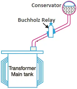
It is usually installed in the pipe connecting the conservator to the main tank as shown in Fig. 1. It is a universal practice to use Buchholz relays on all such oil immersed transformers having ratings in excess of 750 kVA. Its use for oil immersed transformers of rating less than 750 kVA is generally uneconomical.
Construction. Fig. 2 shows the constructional details of a Buchholz relay. It takes the form of a domed vessel placed in the connecting pipe between the main tank and the conservator.
The device has two elements. The upper element consists of a mercury type switch attached to a float. The lower element contains a mercury switch mounted on a hinged type flap located in the direct path of the flow of oil from the transformer to the conservator.
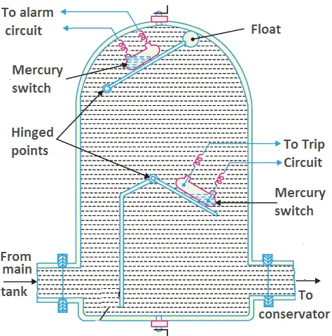
The upper element closes an alarm circuit during incipient faults whereas the lower element is arranged to trip the circuit breaker in case of severe internal faults.
Operation. The operation of Buchholz relay is as follows:-
In case of incipient faults within the transformer, the heat due to fault causes the decomposition of some transformer oil in the main tank. The products of decomposition contain more than 70% of hydrogen gas. The hydrogen gas being light tries to go into the conservator and in the process gets entrapped in the upper part of relay chamber.
When a predetermined amount of gas gets accumulated, it exerts sufficient pressure on the float to cause it to tilt and close the contacts of mercury switch attached to it. This completes the alarm circuit to sound an alarm.
In this condition, there is no need of immediate removal of the transformer from mains. Because sometimes the air bubbles in the oil circulation system even of a healthy transformer may operate the float. For this reason, float is arranged to sound an alarm upon which steps can be taken to verify the gas and its composition.
If a serious fault occurs in the transformer, an enormous amount of gas is generated in the main tank. The oil in the main tank rushes towards the conservator via the Buchholz relay and in doing so tilts the flap to close the contacts of mercury switch. This completes the trip circuit to open the circuit breaker controlling the transformer.
Advantages
- It is the simplest form of transformer protection.
- It detects the incipient faults at a stage much earlier than is possible with other forms of protection.
Disadvantages
- It can only be used with oil immersed transformers equipped with conservator tanks.
- The device can detect only faults below oil level in the transformer. Therefore, separate protection is needed for connecting cables.
Earth-Fault or Leakage Protection
An earth-fault usually involves a partial breakdown of winding insulation to earth. The resulting leakage current is considerably less than the short-circuit current. The earth-fault may continue for a long time and cause considerable damage before it ultimately develops into a short-circuit and removed from the system.
Under these circumstances, it is profitable to employ earth-fault relays in order to ensure the disconnection of earth-fault or leak in the early stage. An earth-fault relay is essentially an overcurrent relay of low setting and operates as soon as an earth-fault or leak develops.
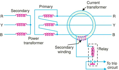
One method of protection against earth-faults in a transformer is the core-balance leakage protection shown in Fig. 3.
The three leads of the primary winding of power transformer are taken through the core of a current transformer which carries a single secondary winding. The operating coil of a relay is connected to this secondary.
Under normal conditions (i.e. no fault to earth), the vector sum of the three phase currents is zero and there is no resultant flux in the core of current transformer no matter how much the load is out of balance. Consequently, no current flows through the relay and it remains inoperative.
However, on the occurrence of an earth-fault, the vector sum of three phase currents is no longer zero. The resultant current sets up flux in the core of the C.T. which induces e.m.f. in the secondary winding. This energises the relay to trip the circuit breaker and disconnect the faulty transformer from the system.
Combined Leakage and Overload Protection
The core-balance protection described above suffers from the drawback that it cannot provide protection against overloads. If a fault or leakage occurs between phases, the core-balance relay will not operate. It is a usual practice to provide combined leakage and overload protection for transformers.
The earth relay has low current setting and operates under earth or leakage faults only. The overload relays have high current setting and are arranged to operate against faults between the phases.
Fig. 4 shows the schematic arrangement of combined leakage and overload protection.
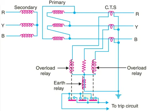
In this system of protection, two overload relays and one leakage or earth relay are connected as shown. The two overload relays are sufficient to protect against phase-to-phase faults. The trip contacts of overload relays and earth-fault relay are connected in parallel. Therefore, with the energising of either overload relay or earth relay, the circuit breaker will be tripped.
Applying Circulating-current System to Transformers
Merz-Price circulating-current principle is commonly used for the protection of power transformers against earth and phase faults. The system as applied to transformers is fundamentally the same as that for generators but with certain complicating features not encountered in the generator application. The complicating features and their remedial measures are briefed below:-
(i) In a power transformer, currents in the primary and secondary are to be compared. As these two currents are usually different, therefore, the use of identical transformers (of same turn ratio) will give differential current and operate the relay even under no load conditions.
The difference in the magnitude of currents in the primary and secondary of power transformer is compensated by different turn-ratios of CTs. If T is the turn-ratio of power transformer, then turn-ratio of CTs on the l.v. side is made T times that of the CTs on the h.v. side.
Fulfilled this condition, the secondaries of the two CTs will carry identical currents under normal load conditions. Consequently, no differential current will flow through the relay and it remains inoperative.
(ii) There is usually a phase difference between the primary and secondary currents of a 3-phase power transformer. Even if CTs of the proper turn-ratio are used, a differential current may flow through the relay under normal conditions and cause relay operation. The correction for phase difference is effected by appropriate connections of CTs.
The CTs on one side of the power transformer are connected in such a way that the resultant currents fed into the pilot wires are displaced in phase from the individual phase currents in the same direction as, and by an angle equal to, the phase shift between the power-transformers primary and secondary currents.
The table below shows the type of connections to be employed for CTs in order to compensate for the phase difference in the primary and secondary currents of power transformer.
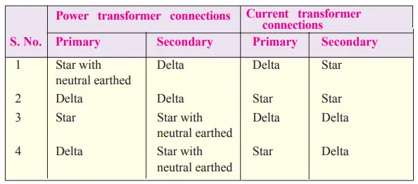
Thus referring to the above table, for a delta/star power transformer, the CTs on the delta side must be connected in star and those on the star side in delta.
(iii) Most transformers have means for tap changing which makes this problem even more difficult. Tap changing will cause differential current to flow through the relay even under normal operating conditions. The above difficulty is overcome by adjusting the turn-ratio of CTs on the side of the power transformer provided with taps.
(iv) Another complicating factor in transformer protection is the magnetising in-rush current. Under normal load conditions, the magnetising current is very small. However, when a transformer is energised after it has been taken out of service, the magnetising or in-rush current can be extremely high for a short period.
Since magnetising current represents a current going into the transformer without a corresponding current leaving, it appears as a fault current to differential relay and may cause relay operation.
In order to overcome above difficulty, differential relays are set to operate at a relatively high degree of unbalance. This method decreases the sensitivity of the relays.
In practice, advantage is taken of the fact that the initial in-rush currents contain prominent second-harmonic component. Hence, it is possible to design a scheme employing second-harmonic bias features, which, being tuned to second-harmonic frequency only, exercise restrain during energising to prevent maloperation.
While applying circulating current principle for protection of transformers, above precautions are necessary in order to avoid inadvertent relay operation.
Circulating Current Scheme for Transformer Protection
Fig. 5 shows Merz-Price circulating-current scheme for the protection of a 3- phase delta/delta power transformer against phase-to-ground and phase-to-phase faults.
Note that CTs on the two sides of the transformer are connected in star. This compensates for the phase difference between the power transformer primary and secondary.
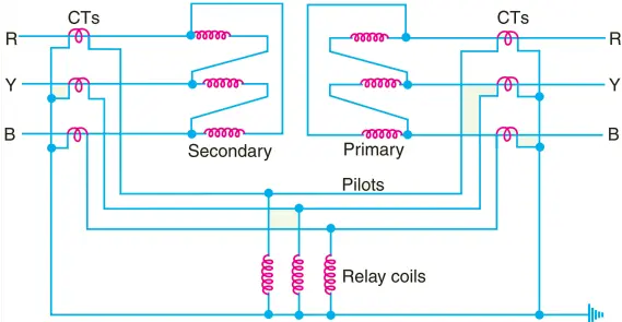
The CTs on the two sides are connected by pilot wires and one relay is used for each pair of CTs.
During normal operating conditions, the secondaries of CTs carry identical currents. Therefore, the currents entering and leaving the pilot wires at both ends are the same and no current flows through the relays.
If a ground or phase-to-phase fault occurs, the currents in the secondaries of CTs will no longer be the same and the differential current flowing through the relay circuit will clear the breaker on both sides of the transformer.
The-protected zone is limited to the region between CTs on the high-voltage side and the CTs on the low-voltage side of the power transformer.
It is worthwhile to note that this scheme also provides protection for short-circuits between turns on the same phase winding.
When a short-circuit occurs between the turns, the turn-ratio of the power transformer is altered and causes unbalance between current transformer pairs.
If turn-ratio of power transformer is altered sufficiently, enough differential current may flow through the relay to cause its operation. However, such short-circuits are better taken care of by Buchholz relays.