Power Factor Correction Equipment
The electrical energy is almost exclusively generated, transmitted and distributed in the form of alternating current. Therefore, the question of power factor immediately comes into picture. Most of the loads (e.g. induction motors, arc lamps) are inductive in nature and hence have low lagging power factor.
The low power factor is highly undesirable as it causes an increase in current, resulting in additional losses of active power in all the elements of power system from power station generator down to the utilisation devices.
In order to ensure most favourable conditions for a supply system from engineering and economical standpoint, it is important to have power factor as close to unity as possible. In this article, we shall discuss the various methods of power factor improvement.
Power Factor
The cosine of angle between voltage and current in an a.c. circuit is known as power factor.
In an a.c. circuit, there is generally a phase difference φ between voltage and current. The term cos φ is called the power factor of the circuit.
If the circuit is inductive, the current lags behind the voltage and the power factor is referred to as lagging. However, in a capacitive circuit, current leads the voltage and power factor is said to be leading.
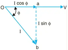
Consider an inductive circuit taking a lagging current I from supply voltage V; the angle of lag being φ. The phasor diagram of the circuit is shown in Fig. 1.
The circuit current I can be resolved into two perpendicular components, namely;
- I cos φ in phase with V
- I sin φ 90o out of phase with V
The component I cos φ is known as active or wattful component, whereas component I sin φ is called the reactive or wattless component.
The reactive component is a measure of the power factor. If the reactive component is small, the phase angle φ is small and hence power factor cos φ will be high.
Therefore, a circuit having small reactive current (i.e., I sin φ) will have high power factor and vice-versa. It may be noted that value of power factor can never be more than unity.
- It is a usual practice to attach the word ‘lagging’ or ‘leading’ with the numerical value of power factor to signify whether the current lags or leads the voltage. Thus if the circuit has a p.f. of 0·5 and the current lags the voltage, we generally write p.f. as 0·5 lagging.
- Sometimes power factor is expressed as a percentage. Thus 0·8 lagging power factor may be expressed as 80% lagging.
Power Triangle
The analysis of power factor can also be made in terms of power drawn by the a.c. circuit. If each side of the current triangle oab of Fig. 1 is multiplied by voltage V, then we get the power triangle OAB shown in Fig. 2
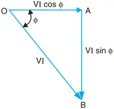
Where,
- OA = VI cos φ and represents the active power in watts or kW
- AB = VI sin φ and represents the reactive power in VAR or kVAR
- OB = VI and represents the apparent power in VA or kVA
The following points may be noted form the power triangle:-
1. The apparent power in an a.c. circuit has two components viz., active and reactive power at right angles to each other.
- OB2 = OA2 + AB2 or
- (apparent power)2 = (active power)2 + (reactive power)2 or
- (kVA)2 = (kW)2 + (kVAR)2
2. Power factor, cos φ = OA/OB = active power/apparent power = kW/kVA
Thus the power factor of a circuit may also be defined as the ratio of active power to the apparent power. This is a perfectly general definition and can be applied to all cases, whatever be the waveform.
3. The lagging* reactive power is responsible for the low power factor. It is clear from the power triangle that smaller the reactive power component, the higher is the power factor of the circuit.
kVAR = kVA sin φ = kW sin φ/cos φ
∴ kVAR = kW tan φ
* If the current lags behind the voltage, the reactive power drawn is known as lagging reactive power. However, if the circuit current leads the voltage, the reactive power is known as leading reactive power.
4. For leading currents, the power triangle becomes reversed. This fact provides a key to the power factor improvement. If a device taking leading reactive power (e.g. capacitor) is connected in parallel with the load, then the lagging reactive power of the load will be partly neutralised, thus improving the power factor of the load.
5. The reactive power is neither consumed in the circuit nor it does any useful work. It merely flows back and forth in both directions in the circuit. A wattmeter does not measure reactive power.
ILLUSTRATION
Let us illustrate the power relations in an a.c. circuit with an example. Suppose a circuit draws a current of 10 A at a voltage of 200 V and its p.f. is 0·8 lagging.
Then,
Apparent power = VI = 200 × 10 = 2000 VA
Active power = VI cos φ = 200 × 10 × 0·8 = 1600 W
Reactive power = VI sin φ = 200 × 10 × 0·6 = 1200 VAR
The circuit receives an apparent power of 2000 VA and is able to convert only 1600 watts into active power. The reactive power is 1200 VAR and does no useful work. It merely flows into and out of the circuit periodically. In fact, reactive power is a liability on the source because the source has to supply the additional current (i.e., I sin φ).
Disadvantages of Low Power Factor
The power factor plays an importance role in a.c. circuits since power consumed depends upon this factor.
P = VI cosφ (For single phase supply)
∴ I = P ÷ Vcos φ
It is clear from above that for fixed power and voltage, the load current is inversely proportional to the power factor. Lower the power factor, higher is the load current and vice-versa. A power factor less than unity results in the following disadvantages:-
(i) Large kVA rating of equipment. The electrical machinery (e.g., alternators, transformers, switchgear) is always rated in kVA.
Now, kVA = kW ÷ cos φ
It is clear that kVA rating of the equipment is inversely proportional to power factor. The smaller the power factor, the larger is the kVA rating. Therefore, at low power factor, the kVA rating of the equipment has to be made more, making the equipment larger and expensive.
(ii) Greater conductor size. To transmit or distribute a fixed amount of power at constant voltage, the conductor will have to carry more current at low power factor. This necessitates large conductor size.
(iii) Larger copper losses. The large current at low power factor causes more I2R losses in all the elements of the supply system. This results in poor efficiency.
(iv) Poor voltage regulation. The large current at low lagging power factor causes greater voltage drops in alternators, transformers, transmission lines and distributors.
This results in the decreased voltage available at the supply end, thus impairing the performance of utilisation devices. In order to keep the receiving end voltage within permissible limits, extra equipment (i.e., voltage regulators) is required.
(v) Reduced handling capacity of system. The lagging power factor reduces the handling capacity of all the elements of the system. It is because the reactive component of current prevents the full utilisation of installed capacity.
The above discussion leads to the conclusion that low power factor is an objectionable feature in the supply system.
Causes of Low Power Factor
Low power factor is undesirable from economic point of view. Normally, the power factor of the whole load on the supply system in lower than 0·8. The following are the causes of low power factor:
- Most of the a.c. motors are of induction type (1φ and 3φ induction motors) which have low lagging power factor. These motors work at a power factor which is extremely small on light load (0·2 to 0·3) and rises to 0·8 or 0·9 at full load.
- Arc lamps, electric discharge lamps and industrial heating furnaces operate at low lagging power factor.
- The load on the power system is varying; being high during morning and evening and low at other times. During low load period, supply voltage is increased which increases the magnetisation current. This results in the decreased power factor.
Power Factor Correction Equipment
The low power factor is mainly due to the fact that most of the power loads are inductive and, therefore, take lagging currents. In order to improve the power factor, some device taking leading power should be connected in parallel with the load. One of such devices can be a capacitor.
The capacitor draws a leading current and partly or completely neutralises the lagging reactive component of load current. This raises the power factor of the load.
Normally, the power factor of the whole load on a large generating station is in the region of 0·8 to 0·9. However, sometimes it is lower and in such cases it is generally desirable to take special steps to improve the power factor. This can be achieved by the following equipment:-
1. Static capacitors. 2. Synchronous condenser. 3. Phase advancers.
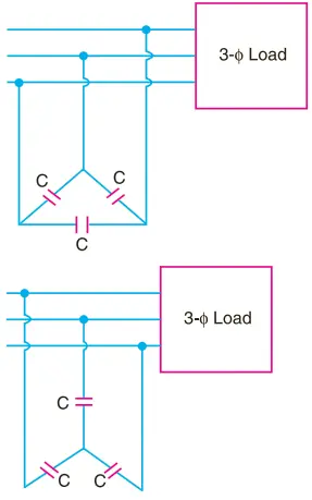
1. Static capacitor. The power factor can be improved by connecting capacitors in parallel with the equipment operating at lagging power factor. The capacitor (generally known as static capacitor) draws a leading current and partly or completely neutralises the lagging reactive component of load current. This raises the power factor of the load. For three-phase loads, the capacitors can be connected in delta or star as shown in Fig. 3. Static capacitors are invariably used for power factor improvement in factories.
Advantages
- They have low losses.
- They require little maintenance as there are no rotating parts.
- They can be easily installed as they are light and require no foundation.
- They can work under ordinary atmospheric conditions.
Disadvantages
- They have short service life ranging from 8 to 10 years.
- They are easily damaged if the voltage exceeds the rated value.
- Once the capacitors are damaged, their repair is uneconomical.
2. Synchronous condenser. A synchronous motor takes a leading current when over-excited and, therefore, behaves as a capacitor. An over-excited synchronous motor running on no load is known as synchronous condenser.
When such a machine is connected in parallel with the supply, it takes a leading current which partly neutralises the lagging reactive component of the load. Thus the power factor is improved. Fig 4 shows the power factor improvement by synchronous condenser method.
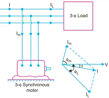
The 3φ load takes current IL at low lagging power factor cos φL. The synchronous condenser takes a current Im which leads the voltage by an angle φm. The resultant current I is the phasor sum of Im and IL and lags behind the voltage by an angle φ. It is clear that φ is less than φL so that cos φ is greater than cos φL. Thus the power factor is increased from cos φL to cos φ. Synchronous condensers are generally used at major bulk supply substations for power factor improvement.
Advantages
- By varying the field excitation, the magnitude of current drawn by the motor can be changed by any amount. This helps in achieving stepless control of power factor.
- The motor windings have high thermal stability to short circuit currents.
- The faults can be removed easily.
Disadvantages
- There are considerable losses in the motor.
- The maintenance cost is high.
- It produces noise.
- Except in sizes above 500 kVA, the cost is greater than that of static capacitors of the same rating.
- As a synchronous motor has no self-starting torque, therefore, an auxiliary equipment has to be provided for this purpose.
Note. The reactive power taken by a synchronous motor depends upon two factors, the d.c. field excitation and the mechanical load delivered by the motor. Maximum leading power is taken by a synchronous motor with maximum excitation and zero load.
3. Phase advancers. Phase advancers are used to improve the power factor of induction motors. The low power factor of an induction motor is due to the fact that its stator winding draws exciting current which lags behind the supply voltage by 90o.
If the exciting ampere turns can be provided from some other a.c. source, then the stator winding will be relieved of exciting current and the power factor of the motor can be improved. This job is accomplished by the phase advancer which is simply an a.c. exciter.
The phase advancer is mounted on the same shaft as the main motor and is connected in the rotor circuit of the motor. It provides exciting ampere turns to the rotor circuit at slip frequency. By providing more ampere turns than required, the induction motor can be made to operate on leading power factor like an over-excited synchronous motor.
Phase advancers have two principal advantages. Firstly, as the exciting ampere turns are supplied at slip frequency, therefore, lagging kVAR drawn by the motor are considerably reduced. Secondly, phase advancer can be conveniently used where the use of synchronous motors is inadmissible.
However, the major disadvantage of phase advancers is that they are not economical for motors below 200 H.P.
Benefits of Power Factor Correction
The improvement of power factor is very important for both consumers and generating stations as discussed below:-
(i) For consumers. A consumer has to pay electricity charges for his maximum demand in kVA plus the units consumed. If the consumer imporves the power factor, then there is a reduction in his maximum kVA demand and consequently there will be annual saving due to maximum demand charges.
Although power factor improvement involves extra annual expenditure on account of p.f. correction equipment, yet improvement of p.f. to a proper value results in the net annual saving for the consumer.
(ii) For generating stations. A generating station is as much concerned with power factor improvement as the consumer. The generators in a power station are rated in kVA but the useful output depends upon kW output. As station output is kW = kVA × cos φ, therefore, number of units supplied by it depends upon the power factor.
The greater the power factor of the generating station, the higher is the kWh it delivers to the system.
This leads to the conclusion that improved power factor increases the earning capacity of the power station.
Most Economical Power Factor
If a consumer improves the power factor, there is reduction in his maximum kVA demand and hence there will be annual saving over the maximum demand charges.
However, when power factor is improved, it involves capital investment on the power factor correction equipment. The consumer will incur expenditure every year in the shape of annual interest and depreciation on the investment made over the p.f. correction equipment.
Therefore, the net annual saving will be equal to the annual saving in maximum demand charges minus annual expenditure incurred on p.f. correction equipment.
The value to which the power factor should be improved so as to have maximum net annual saving is known as the most economical power factor.
In actual practice, it is quite economical to work with an average p.f. of 0.92 – 0.95, as the advantages accruing from higher p.f. are counter balanced by the additional investment in power factor correction equipment.