Bus Bar Arrangement in Substation
When a number of generators or feeders operating at the same voltage have to be directly connected electrically, bus-bars are used as the common electrical component. Bus-bars are copper rods or thin walled tubes and operate at constant voltage.
In this article, we shall discuss some important bus-bars arrangements used for power stations and sub-stations. All the diagrams refer to 3-phase arrangement but are shown in single-phase for simplicity.
Single Bus Bar System
The single bus-bar system has the simplest design and is used for power stations. It is also used in small outdoor stations having relatively few outgoing or incoming feeders and lines.
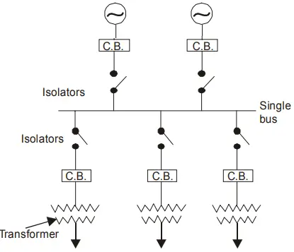
Fig. 1. shows the single bus-bar system for a typical power station. The generators, outgoing lines and transformers are connected to the bus-bar. Each generator and feeder is controlled by a circuit breaker. The isolators permit to isolate generators, feeders and circuit breakers from the bus-bar for maintenance.
The chief advantages of this type of arrangement are low initial cost, less maintenance and simple operation.
Disadvantages: Single bus-bar system has the following three principal disadvantages:-
- The bus-bar cannot be cleaned, repaired or tested without de-energizing the whole system.
- If a fault occurs on the bus-bar itself, there is complete interruption of supply.
- Any fault on the system is fed by all the generating capacity, resulting in very large fault currents.
Single Bus Bar with Sectionalisation
In large generating stations where several units are installed, it is a common practice to sectionalise the bus so that fault on any section of the bus-bar will not cause complete shutdown.
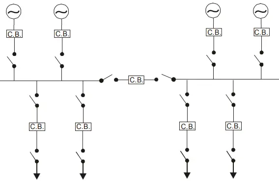
This is illustrated in Fig. 2. which shows the bus bar divided into two sections connected by a circuit breaker and isolators. Three principal advantages are claimed for this arrangement.
- Firstly, if a fault occurs on any section of the bus-bar, that section can be isolated without affecting the supply to other sections.
- Secondly, if a fault occurs on any feeder, the fault current is much lower than with unsectionalized bus-bar. This permits the use of circuit breakers of lower capacity in the feeders.
- Thirdly, repairs and maintenance of any section of the bus-bar can be carried out by de-energizing that section only, eliminating the possibility of complete shutdown.
It is worthwhile to keep in mind that a circuit breaker should be used as the sectionalizing switch so that uncoupling of the bus-bars may be carried out safely during load transfer. Moreover, the circuit breaker itself should be provided with isolators on both sides so that its maintenance can be done while the bus-bars are alive.
Duplicate Bus Bar Arrangement
In large stations, it is important that breakdowns and maintenance should interfere as little as possible with continuity of supply.
In order to achieve this objective duplicate bus-bar system is used in important stations. Such a system consists of two bus-bars, a “main bus-bar and a “spare” bus-bar (see Fig. 3).
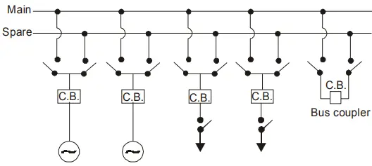
Each generator and feeder may be connected to either bus-bar with the help of bus coupler which consists of a circuit breaker and isolators. In the scheme shown in Fig. 3, service is interrupted during switch over from one bus to another.
However, if it were desired to switch a circuit from one to another without interruption of service, there would have to be two circuit breakers per circuit. Such an arrangement will be too expensive.
Advantages:
- If repair and maintenance it to be carried on the main bus, the supply need not be interrupted as the entire load can be transferred to the spare bus.
- The testing of feeder circuit breakers can be done by putting them on spare bus-bar, thus keeping the main bus-bar undisturbed.
- If a fault occurs on the bus-bar, the continuity of supply to the circuit can be maintained by transferring it to the other bus-bar.
Bus Bar Protection
Bus-bars and lines are important elements of electric power system and require the immediate attention of protection engineers for safeguards against the possible faults occurring on them. The methods used for the protection of generators and transformers can also be employed, with slight modifications, for the bus-bars. The modifications are necessary to cope with the protection problems arising out of a large number of circuits connected to a bus-bar.
Bus-bars in the generating stations and sub-stations form important link between the incoming and outgoing circuits. If a fault occurs on a bus-bar, considerable damage and disruption of supply will occur unless some form of quick-acting automatic protection is provided to isolate the faulty bus-bar.
The bus-bar zone, for the purpose of protection, includes not only the bus-bars themselves but also the isolating switches, circuit breakers and the associated connections.
In the event of fault on any section of the bus-bar, all the circuit equipment’s connected to that section must be tripped out to give complete isolation. The standard of construction for bus-bars has been very high, with the result that bus faults are extremely rare.
However, the possibility of damage and service interruption from even a rare bus fault is so great that more attention is now given to this form of protection. Improved relaying methods have been developed, reducing the possibility of incorrect operation. The two most commonly used schemes for bus-bar protection are:
- Differential protection
- Fault bus protection.
Differential Protection of Bus Bars
The basic method for bus-bar protection is the differential scheme in which currents entering and leaving the bus are totalised. During normal load condition, the sum of these currents is equal to zero. When a fault occurs, the fault current upsets the balance and produces a differential current to operate a relay Fig. 4. shows the single line diagram of current differential scheme for a station bus-bar.
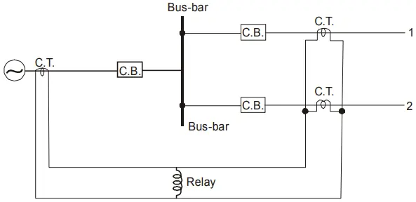
A generator and supplies load to two lines feeds the bus-bar. The secondaries of current transformers in the generator lead, in line 1 and in line 2 are all connected in parallel. The protective relay is connected across this parallel connection. All CTs must be of the same ratio in the scheme regardless of the capacities of the various circuits.
Under normal load conditions or external fault conditions, the sum of the currents entering the bus is equal to those leaving it and no current flows through the relay.
If a fault occurs within the protected zone, the currents entering the bus will no longer be equal to those leaving it. The difference of these currents will flow through the relay and cause the opening of the generator, circuit breaker and each of the line circuit breakers.
Fault Bus Protection
It is possible to design a station so that the faults that develop are mostly earth-faults. This can be achieved by providing earthed metal barrier (known as fault bus) surrounding each conductor throughout its entire length in the bus structure.
With this arrangement, every fault that might occur must involve a connection between a conductor and an earthed metal part. By directing the flow of earth-fault current, it is possible to detect the faults and determine their location. This type of protection is known as fault bus protection.
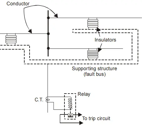
Fig. 5. shows the schematic arrangement of fault bus protection. The metal supporting structure or fault bus is earthed through a current transformer. A relay is connected across the secondary of this CT.
Under normal operating conditions, there is no current flow from fault bus to ground and the relay remains inoperative. A fault involving a connection between a conductor and earthed supporting structure will result in current flow to ground through the fault bus, causing the relay to operate. The operation of relay will trip all breakers connecting equipment to the bus.