Electrical Insulation Resistance Test
This test can be carried out on a complete installation, a group of circuits or on a single circuit, whichever is most suitable for the installation being tested. This test is carried out to find out if there is likely to be any leakage of current through insulated parts of the installation. A leakage could be between live parts or live parts to earth.
As we know voltage can be related to pressure and that the pressure of our low voltage single phase supply is 230 volts a.c. When we carry out an insulation resistance test on a standard installation we must use a test voltage of 500 volts d.c. This is more than double the normal voltage and what we are doing can be related to a pressure test to identify any leaks.
Causes of Low Insulation Resistance
Cable insulation can deteriorate due to the age and type of cable insulation. The older type of rubber insulated cables tend to get very brittle where the outer mechanical protection has been removed leaving the insulated conductors exposed, and this often causes a low installation resistance.
Other causes due to cables could be where cables are crushed under floor boards, clipped on the edge or even worn very thin due to being pulled through holes in joists where other cables are present.
A low insulation resistance will indicate this type of damage. It will also often be found where the building has been left unused for a long period of time, particularly around cold and damp times of the year as dampness can creep into the accessories. In buildings which have just been plastered such as new build or renovations it is not unusual to get low readings due to the moisture in the walls causing dampness in switches or socket outlets. And of course it is very important that all of these conditions are identified.
Low resistance values can also be recorded where there are long cable runs or even where circuits are measured together in parallel, due to the amount of insulation being tested. (The longer the cables or the greater the number of circuits, in theory there is more insulation for the test current to leak through.)
The instrument used for this test is called an insulation resistance tester. The tester has to meet certain requirements which are set by the Health and Safety Executive and these are that it must be capable of maintaining a test voltage of 500 volts d.c. and a current of 1mA when applied to a resistance of 1MΩ.
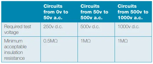
Above Table shows the minimum acceptable insulation resistance values for circuits operating at various voltages, remember that this is a pressure test. This means that in most cases the test voltage should be greater than the operating voltage of the circuit, although under some circumstances this may be reduced due to the type of circuit or equipment connected to it.
During an initial verification it is important that all conductors are tested, as under some circumstances this is impossible to do once the work is fully completed. Always remember that inspecting testing should be carried out during erection and on completion. One of the reasons for this is that once some pieces of equipment are connected, such as fluorescent lamps or transformers, it is impossible to test between live conductors as the load will have the effect of giving a poor reading.
Another good reason for carrying out insulation tests on cables is to check that they are not damaged before they are covered by building materials. This is particularly important on jobs that are slow to progress, and where parts of the installation are left for weeks on end without being worked on by the electrician.
Under these circumstances the cables are pretty vulnerable and can easily be damaged – it is better that you find out while you have an opportunity to carry out the repair without having to take floors up or ceilings down.
Testing the Whole Installation
During an initial verification, particularly a domestic one, it is often easier to carry out the insulation test at the ends of the meter tails before they are connected to the supply. If the testing has been ongoing during the installation you will have a reasonable idea of the sort of values which you will be expecting to measure – hopefully very high!
As with any kind of dead test, ensure the system is dead. In this case it will be as the tails are not connected.
First check that the insulation resistance tester is working by testing it with the leads joined and then apart; with the leads together the reading should be 0.00Ω and when apart it should be over range.
Before proceeding with the test,
- Ensure the tester is accurate and that the test leads are compliant with GS 38.
- Set the tester to 500 volts d.c. ready for the test.
- Check that the protective devices are in place and are switched on.
- Remove all lamps from fittings where accessible.
- Providing testing has been ongoing, and lamps are not accessible, ensure that the switch controlling the luminaires is open (off); this also applies to luminaires with control gear such as fluorescent fittings. When testing installations which have not been subjected to testing during the installation, the luminaires must be disconnected and all of the conductors must be tested (note 1). The same applies where extra low voltage transformers are fitted.
- Where dimmer switches are fitted it is important that they are either removed and the switch wires joined together, or the switch can be linked across or bypassed (note 2).
- Any accessories which have neon indicator lamps fitted are switched off (note 3).
- Passive infra red detectors (PIRs) are removed, bypassed or linked out (note 4).
- All fixed equipment such as cookers, immersion heaters, heating circuits for boilers, TV amplifiers etc. are isolated.
- Shaver sockets are disconnected or isolated (note 5).
- All items of portable equipment are unplugged.
NOTES
- The control equipment inside discharge lamps will cause very low insulation resistance readings. It is quite acceptable to isolate the fitting by turning off the switch; this is far more desirable than disconnecting the fitting. After the test between live conductors has been carried out, the control switch for the luminaire should be closed before carrying out the test between live conductors and the CPC. This is to ensure that all of the conductors are tested for insulation resistance to earth.
- Most dimmer switches have electronic components in them and these could be damaged if 500v were to be applied to them. It is important that wherever possible dimmer switches are removed and the line and switch return are joined together for the test.
- The test will also return a very low reading if neon indicator lamps are left in the circuit as they will be recognized as a load. All that is required is that the accessory is switched off.
- Passive infrared detectors, light sensitive switches will also give very low readings and will be damaged by the test voltage. Either disconnect them, link them out or just test between live conductors and earth only.
- Shaver sockets can also cause a problem, the best way to deal with them is to disconnect either the line or the neutral.
- Wherever you are unsure of what is connected to the circuit it is always better to test at 250 volts first; if the reading is low do not proceed with the test until the reason for the low reading is identified.
Electrical Insulation Resistance Test
- Step 1: Set the insulation resistance tester to the required test voltage; for most low voltage circuits this will be 500 volts d.c.
Some instruments have settings for MΩ and some are self-ranging. Where they require setting, 200MΩ or above is the most suitable setting to use.
- Step 2: Always check that the tester is working correctly by testing with the leads apart. The reading shown should be the highest that the tester should measure.
- Step 3: Now join the leads together and operate the tester again. This should produce a reading of 0.00MΩ which is the lowest that the tester will read. This proves that the tester is working and that the leads are not broken.

- Step 4: When testing a complete installation there are options as to how the test is carried out – you can test from the tails if it is a new installation which has not been connected, or you can test from the dead side of the main switch if the installation has been connected. An example would be a rewire. Ensure that all of the circuit breakers are in the on position or if the installation is protected by fuses make sure that they are all in place. Where the test is being carried out at the main switch, make sure that it is in the off position and locked off. Test between live conductors and operate any two way switching. This is to ensure that the strappers of the circuit are tested and it will also ensure that the switch returns have been correctly identified and connected (no neutrals in the switches).
- Step 5: Test between live conductors and earth. This can be by joining together the live conductors, or if testing at the main switch it can be carried out between each conductor individually. Again it is important to operate any two way switches. As the test is being carried out the measured values should be entered on to the schedule of test results.

The acceptable insulation resistance as being 1MΩ, this is for a single circuit or a complete installation. Guidance note 3 recommends that any circuit giving a value of 2MΩ or less must be investigated; this is because a value as low as 2MΩ may indicate a latent defect which could develop into a major problem at a later date.
Although these values will comply with the requirements of BS 7671, they are still very low values for the majority of circuits. Consideration must be given as to why the circuit insulation resistance is low, where the circuit is new it is very unlikely that a reading of 2MΩ would be acceptable. Even on an older existing circuit there would need to be a good reason why the value is so low, and it would need to be monitored to check that it was not getting worse.
Where the whole installation is being tested in one go and a low reading is measured, it is a good idea to test each circuit individually, as this will identify whether it is on a circuit causing the problem or an accumulation of the insulation resistance of circuits being measured in parallel.
In theory the more circuits in parallel the lower the reading will be, although in practice it really should not make much difference providing the circuits are in good condition.
On some occasions a low value may be acceptable, often where a building has been empty for a long period of time, particularly in the winter, or perhaps some of the installation is outside or underground cables have been installed. Whatever the case may be, it is important that you have some idea of why low readings, although acceptable, are being recorded as it may be indicating a problem for the future. Of course in the case of an unused installation the insulation resistance will probably rise after a period of use.
In all cases where insulation resistance tests are carried out it is important that the results are thought about and not just recorded; an element of careful thought and sensible judgment has to be part of the testing process.
Where a complete installation is tested from the tails or main switch and an acceptable value is measured, it is permissible to enter the same value for all of the circuits on the schedule of test results.
Testing of Individual Circuits
On existing installations or even some new installations it may be necessary to test each circuit individually, particularly where the complete installation cannot be isolated. The same safety precautions must be taken. Always ensure that the circuit to be tested has been safely isolated by removing the fuse or turning off the circuit breaker; always follow the isolation procedure and make sure that the circuit is locked off, and that you are the only person who can switch it back on. It will be necessary to disconnect the neutral of the circuit being tested; this is because all of the neutrals are connected into a common terminal.
On installations which have to remain live, any neutral connected to the neutral bar will also be connected to the star point of the supply transformer, which in turn is connected to earth. This of course will produce a very low reading between neutral and earth.
It is also very important when testing an individual circuit that the earthing conductor for the circuit remains connected to the main earthing terminal, along with any bonding conductors which have been installed. This is because that if it is disconnected, and there is a fault on the circuit between a live conductor and any exposed or extraneous metal work, it will only show up if the CPC is connected.
Check that all equipment which may be vulnerable to testing, or any equipment which may produce a low reading is disconnected or isolated.
Remember if in doubt about what may be connected, test at 250 volts first.
Carry out the checks on the tester and leads to ensure its correct operation. As previously mentioned, if the main switch is off then the tests can be carried out without disconnecting the conductors. They will only need to be disconnected if the measured value is low, it may be that the low reading is not on the circuit which is being tested. This is because all of the neutrals and all of the CPCs are connected into common terminals.
Test between live conductors and then live conductors and earth.
When testing between live conductors and earth the live conductors can be joined together, and then tested to earth or they can be tested separately, whichever is easiest.
Where for some reason a piece of equipment connected to the installation cannot be isolated from the circuit being tested, do not carry out the test between live conductors, only test between live conductors and earth. This will avoid damage to the equipment due to the test voltage. This test method should only be carried out on individual circuits and not on a whole installation, it is important that as much of the installation is tested as possible.
Effect of Surge Protection on Insulation Resistance
Where a circuit has surge protection an insulation test can give very low readings; this will of course look like there is a fault when in fact it is really just that surge protection has been fitted. Where possible it is better to disconnect the surge protection; however where this is not an option, it is perfectly acceptable to test at 250v d.c. and record the values obtained.
Insulation Resistance Testing of 3 Phase Installation
When carrying out an insulation resistance test on a three phase installation all of the same precautions and procedures apply as for a single phase installation or circuit. Where the test is for the whole installation the test can be carried out on the isolated side of the main switch. Safe isolation must be carried out before beginning the test and all of the protective devices must be in the on position.
- Step 1: Set the tester to 500v d.c.
- Step 2: Test between all line conductors.
- Step 3: Test between all line conductors and neutral; the line conductors can be joined together for this part of the test.
- Step 4: Test between all live conductors to earth; the line and N conductors can be linked for this part of the test, or the test can be carried out between each line to earth and then the neutral to earth.
When testing a 3 phase installation the minimum resistance values are the same as for single phase installations. The minimum acceptable is 1MΩ although any values below 2MΩ must be investigated.
- Step 5: Remove any links which have been used to simplify the testing process.
On occasions where it is only possible to test each circuit individually, it is still very important to ensure that the insulation resistance for the whole installation does not fall below the minimum acceptable value which of course is 1MΩ. Under these circumstances a calculation must be carried out.
EXAMPLE: An installation consisting of six circuits is tested as a whole; the insulation resistance between live conductors and earth is 1.9MΩ.
The installation is split and each circuit is now tested individually. All of the circuits are found to be between 100 and 200MΩ apart from one.
On investigation it is found that the circuit causing the low reading is a mineral insulated cable supplying a lamp post in the garden, so it could be that the connection to the lamp is damp or has condensation in it.
In this case it is easily rectified; in cases where the problem is not so easily found the circuit should be monitored, as often if a circuit which is wired with mineral insulated cable is left switched on with a load connected it will dry out naturally.
EXAMPLE: A consumer’s unit has six circuits which when measured for insulation resistance between live conductors and earth.
- Circuit 1 is 140MΩ
- Circuit 2 is 70MΩ
- Circuit 3 is 10MΩ
- Circuit 4 is 8MΩ
- Circuit 5 is 200MΩ
- Circuit 6 is 45MΩ
We now need to carry out a calculation to check that the insulation resistance value of the total installation;
The calculation is: 1/R1 + 1/R2 + 1/R3 + 1/R4 + 1/R5 + 1/R6 = 1/Rt
Put in the values: 1/140 + 1/70 + 1/10 + 1/8 + 1/200 + 1/45 = 0.27
Now, 1/Rt = 0.27
Rt = 1/0.27 = 3.65MΩ
This value is greater than 1MΩ and is satisfactory.