The three most commonly used electrical test instruments are: the clamp-on amp meter, the AC voltmeter, and the Ohmmeter. These three meters are commonly known today as digital multimeters (DMM). It is vitally important that electrical personnel know how to correctly use a DMM.
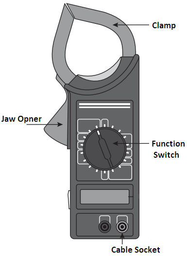
These meters are used to not only understand how an electrical system is functioning but also they are very important to the safety of personnel working on and around electrical equipment. Figure 1 is a common DMM. Today digital multimeters of all types are the most commonly used.

Words used with meters: Much of the time meters can be used for various tasks, such as measuring AC and DC voltage, AC and DC amperage, and electrical resistance of a circuit. For this reason, most of the time a meter will be a multifunctional measuring instrument. Some call them voltmeters, some multimeters or DMM, while others will simply say meter.
In this article, “multimeter” is used for a meter that can measure AC or DC voltage and electrical resistance, which is measured in ohms. When speaking about a meter that can measure amperage, “amp meter” will be used to indicate a clamp-on type meter. When a meter can measure resistances in the millions of ohms, at DC test voltages of 250, 500, or 1,000 VDC, “meg-ohm meter” is used.
Many of the modern family of electrical test instruments can perform additional measurement tasks in addition to the ones that will be covered in this article.
DIGITAL MULTIMETER HOW TO USE IT?
As electrons cannot be seen, a voltmeter is needed to measure the pressure in an electrical circuit in units of measurement called volts (V). In this article, only alternating current voltages (VAC) will be considered. While many can, not all meters can measure direct current (DC) voltages.
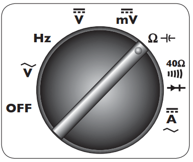
On some meters, the letters AC and DC are preceded by the letter V on the meter’s function selector scale. A tilde is used on some meters to indicate AC voltages. Some meters will use a solid line with three or more dots below it to indicate the DC voltage function.
VOLTAGE FUNCTION
Of all the functions electrical meters can perform, the most important is the measurement of VAC, as it is the most important to the safety of personnel. The maximum voltage of both the meter and its test leads must not be exceeded.
While some cannot, many multimeters can read up to 600 VAC. Check the meter before it is used, as it could be destroyed by applying it to a voltage outside its design limits.
AUTO-RANGING METERS
Figure 2 shows the function selector switch found on a typical DMM. Some of the better quality meters can automatically measure volts and millivolts. These meters will many times automatically select the correct voltage range using either a volts or millivolts scale.

This can lead to confusion when one is not accustomed to this feature. This makes it important to carefully look at the meter’s display to confirm the range being used.
For example, a machine is being checked to see if it has a voltage before being serviced, and the multimeter’s test leads are connected to two test points, and the meter displays 87. This only could be 87 millivolts. When the letters mV are displayed, this indicates that there is essentially only a static voltage present.
When an AC voltage is applied to a meter set to the DC voltage function, it may not display any value, or it may do something strange. Make sure the meter is set to the proper function as it can be destroyed in an instant.
THREE-STEP METHOD
All man-made things can fail, and delicate instruments can fail internally without any indication on the outside. Always practice the three-step method when checking for voltage:
- Step 1, test the meter on a known live circuit.
- Step 2, test the circuit to be tested.
- Step 3, test the meter again on a known live circuit.
HOW TO DESTROY A MULTIMETER
A multimeter can be instantly destroyed by placing the meter on the ohms function and applying the two test leads to a circuit that has a voltage. In an instant, boom, pop, and all of the magic smoke escapes from the meter. This is most likely to occur when one is under pressure to get a machine up and running.
AUTO FUNCTION FEATURES
Some of the better meters can automatically select the desired function, such as measuring volts or ohms. These meters have only an on-off selector switch. When turned on and the two test leads are applied to the circuit, the “internal brain” of the multimeter automatically selects the proper function, volts or ohms, and the correct range.
While the battery life of multimeters is good, at some point they will discharge. Place a spare battery in the case with the multimeter as the battery will likely fail when it is needed most.
LEATHER GLOVES
Find an electrician, and ask if he or she has ever been shocked. Then ask if he or she has ever been shocked while wearing a pair of leather work gloves. Some electricians do not always follow the safe work practice of using double-insulated gloves. Some companies do not provide them. Make it a lifesaving good habit of putting on at least a pair of leather work gloves before using a multimeter.
Use these gloves only when using a multimeter. Special double-insulated electricians’ gloves are always the best choice for protection from electrical shock. Leather work gloves without any metal trim are better than exposing bare skin to potential shock hazards.
OHMMETERS
This function of a multimeter measures the opposition to the flow of electrons in units of measurement called ohms. An upside-down letter u, or a horseshoe, is used to indicate the ohm function on a meter. One of the rules of electricity requires the current flow (measured in amperes, or amps—A) to decrease when the resistance increases. An ohmmeter is used to measure this resistance. Before an ohmmeter is connected to any circuit, there must not be any voltage present.
Capacitors must be discharged. First, test to confirm that there is no voltage present. If a reading other than the system’s rated voltage is found, inspect the system for the presence of a capacitor. When one is located, it must be safely discharged. This can be done by shorting one capacitor terminal to the other capacitor terminal. Be careful, as there will be a small spark and a pop sound. Use only an insulated section of electrical wire for this task.
Ohmmeters have ranges over which they will read resistances accurately. Common scales are 200, 2,000, 20,000 (20K), 200K, and 2,000K (2 meg-ohms).
When the meter is set on the 200-ohm scale and is used to measure the 250-ohm resistor, it may display the letters OL, or the number one. Both are used to indicate that the measured value is more than the scale setting.
Ohmmeters are used to determine the amount of resistance between two points, for example, the two wires of an extension cord. While these insulated wires are physically touching each other, they should not be electrically touching each other.
The resistance of many types of modern electrical insulation is about 150 volts per mill (1/1,000 of one inch) of insulation thickness. It is not uncommon for individual electrical wires to be insulated with 15 or more mills of insulation covering them.
When an ohmmeter is used to measure the resistance of insulated wires in an extension cord, the resistance should be in the millions of ohms. Over time all electrical insulation ages and loses some of its electrical insulating ability, that is, its dielectric strength decreases. This is just part of the normal aging process. When a defect in electrical insulation occurs in one small area, electrons will begin to leak through the defect, allowing more and more current to flow. This is known as a short circuit. The ohmmeter function of a multimeter is used to locate short circuits in electrical devices such as wires, motors, and transformers.
A short to ground can be located by placing one test lead on the case ground (any metal part of the machine) and placing the other test lead on each of the suspected wires one at a time. As a general rule, a value less than 1 million ohms indicates that the conductor is shorted to the ground.
If all of the insulated wires are healthy, they will tend to read over 1 million ohms. The one wire that indicates a very low resistance value is most likely the cause of the trouble and should be investigated further.
Three-phase motors draw electrical energy from the three power supply wires equally. So the resistance between each should be very close to the same value. Using the ohm function of a multimeter, a measurement from each of the motor’s leads (wires) to each other, the meter should display the same value. Any reading of more than a 5 percent difference should be investigated.
When a load such as a motor has a winding that has shorted open, the resistance will be over 1 million ohms. When a load such as a transformer has shorted a winding to itself, the resistance will be very low, typically less than one ohm.
MEG-OHMMETER
A meg-ohmmeter (known as a “megger”) is a basic ohmmeter with the added ability to measure resistances in the millions of ohms. A meg is equal to 1 million. Meggers typically can measure resistances as high as 1,000 or more meg-ohms, whereas the typical ohmmeter can measure only values up to about 5 meg-ohms.
Never test any machine that has some type of solid-state device in it with a megger. To do so will instantly destroy these sensitive components. Disconnect all electronic devices before “megging” any circuit. Meggers typically have selectable test voltages of 250, 500, 1,000, and some as high as 4,000 VDC.
CLAMP-ON AMP METERS
When current flows over an electrical wire, a magnetic field is produced. That is, the wire becomes electromagnetic.
The intensity strength of this field increases as the amount of current flow increases. An amp meter is used to measure this magnetic field without being electrically connected to the circuit being tested. Clamp-on amp meters are opened and then placed around one wire and then closed. The meter senses the strength of the magnetic field and displays the measured value on the meter’s display in amperes.
Electrical motors typically have an amperage value listed on the motor’s nameplate. This may be listed as either RLA, for rated load amps, or FLA for full load amps, both being the same value.
When a three-phase motor is fully loaded, it will pull full-load amps. When the motor is overloaded, it will pull more than rated load amps. And when it is unloaded it will pull less than full-load amps.
Clamp-on amp meters, like all test equipment, are used to provide answers to the electrician’s questions. For example, is this motor fully loaded or overloaded? Are all three phases of this motor pulling the same amount of current? The amp meter can quickly be used to obtain answers to these important questions.
There are lots of different brands and models of multimeters, Meggers, and clamp-on amp meters available today. Some sell for only a few dollars, others for thousands of dollars. When selecting a meter, look for features that will be routinely used, such as AC volts to 1,000 AC amps to 1,000 resistance values to 5 meg-ohms. Then consider the category of the meter.
For general commercial and industrial work, where 460 V and short-circuit amperages in the 1,000s will be encountered, a Category III or higher meter should be selected.
Electricians routinely check a machine for the presence of a voltage. Often, when they say there is no voltage present, they feel it is safe to touch the circuit’s wires and components bare-handed. Electrical test instruments should be selected as one would any piece of life safety equipment.
HOW A DIGITAL MULTIMETER WORKS
In a digital multimeter, the analogue quantity to be measured (current, voltage, resistance) is firstly transformed into an equivalent voltage if the parameter to be measured is current or resistance. The transformed analogue voltage is then digitized using an A/D converter (ADC).
To be more precise, the analogue voltage is converted into a pulse train whose frequency depends upon the magnitude of the voltage. The pulses are counted over a known gating period in a counter. The counter outputs are decoded and displayed. The displayed count represents the magnitude of the parameter under measurement.
In another approach that is also in common use the input analogue voltage is compared with a ramp from a ramp generator. The comparator generates a gating pulse whose width equals the time interval between the ramp amplitude rising from zero to the analogue voltage under measurement. The counter in the ADC counts clock pulses of a known frequency over this gating interval, and the counter count is decoded and displayed.
Thus, while in the former method there is a voltage-to-frequency (V/F) conversion and the equivalent frequency representing the analogue voltage is counted over a fixed gating interval, in the latter method a fixed frequency is counted over a variable gating interval, with the gating interval being proportional to the analogue voltage.
INSIDE THE DIGITAL METER
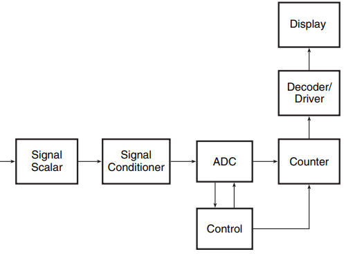
Figure 3 shows the schematic arrangement of a typical digital meter. The signal scalar at the input is basically an attenuator/amplifier block and is partly used for range selection function.

In autoranging meters, the input signal level is sensed on application of the input signal, and the signal scalar gain is selected accordingly. The signal conditioner generates a DC voltage proportional to the input signal.
The ADC employed is usually the integrating-type ADC, single slope or dual slope, with the latter being the preferred one because of its higher accuracy, insensitivity to changes in integrator parameters and low cost. All the building blocks depicted in Fig. 3, except for the display, are available on a single chip. ICL 7106/7107 is an example.
SIGNIFICANCE OF THE HALF-DIGIT
Digital multimeters (DMMs) invariably have a display that has an additional half-digit. We have 3-1/2, 4-1/2 and 5-1/2 digit digital multimeters rather than 3-, 4- and 5-digit multimeters.
While the usually so-called full digits can display all digits from 0 to 9, a half-digit can display either a ‘0’ or a ‘1’. The addition of a half-digit in the MSB position of the display preserves the resolution of the multimeter up to a higher range.
For instance, a three-digit multimeter has a resolution of 0.1 V up to 99.9 V. A 3-1/2-digit meter with practically no additional hardware would give you a resolution of 0.1 V up to 199.9 V. This increase in resolution range comes with the addition of one additional seven-segment display and no change in hardware complexity. The display resolution is also sometimes expressed in terms of counts. The 3-1/2 digit DMM has a 2000 count resolution.
DMMs with a 4000 count resolution, referred to as 3-3/4 digit meters, are also commercially available. These meters will also have four seven-segment displays but have some additional hardware.
Digital multimeters are made in a large variety of sizes, shapes and performance specifications, ranging from pen-type 3-1/2 digit DMMs to 7-1/2 digit high-resolution benchtop versions. Handheld versions are available, typically up to 4-1/2-digit resolution. The majority of them have an in-built diode test, transistor test and continuity check features. Some of them even offer L-C measurement and frequency measurement without any significant change in price.
ADVANTAGES OF USING A DIGITAL MULTIMETER
The digital multimeter has the advantages of offering unambiguous display with no allowance for any human error, improved accuracy (±01% as against ±3% in analogue meters) and improved resolution (+01% as against 1% in analogue meters).
Other advantages include easy incorporation of features such as autoranging, automatic polarity and diode/transistor test and so on.
The cost advantage that used to exist in favour of analogue meters has narrowed down to a small amount with advances in IC technology.
Digital multimeters are fast replacing analogue meters even for routine measurements. However, analogue meters are relatively immune to noise and are preferred in an electrically noisy environment.