Electric Braking of Motors
There are three types of electric braking as applicable to electric motors.
- Plugging or reverse-current braking.
- Rheostatic or dynamic braking.
- Regenerative braking.
In many cases, provision of an arrangement for stopping a motor and its driven load is as important as starting it. For example, a planing machine must be quickly stopped at the end of its stroke in order to achieve a high rate of production.
In other cases, rapid stops are essential for preventing any danger to operator or damage to the product being manufactured. Similarly, in the case of lifts and hoists, effective braking must be provided for their proper functioning.
Plugging of D.C. Motors
In this case, armature connections are reversed whereas field winding connections remain unchanged. With reversed armature connections, the motor develops a torque in the opposite direction.
When speed reduces to zero, motor will accelerate in the opposite direction. Hence, the arrangement is made to disconnect the motor from the supply as soon as it comes to rest.
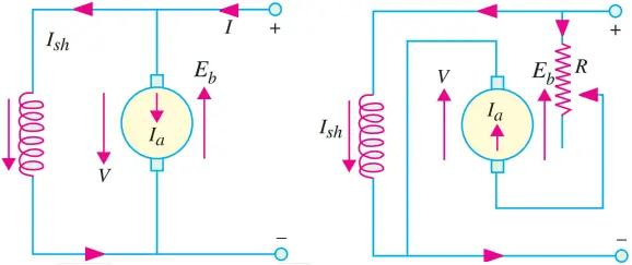
Fig. 1 shows running and reversed connections for shunt motors whereas Fig. 2 shows similar conditions for series motors.
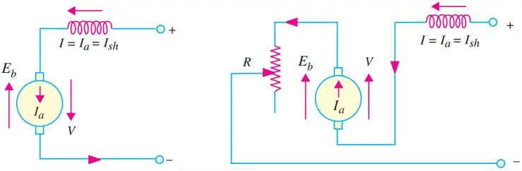
Since with reversed connection, V and Eb are in the same direction, voltage across the armature is almost double of its normal value. In order to avoid excessive current through the armature, additional resistance R is connected in series with armature.
This method of braking is wasteful because in addition to wasting kinetic energy of the moving parts, it draws additional energy from the supply during braking.
Plugging of Induction Motors
This method of braking is applied to an induction motor by transposing any of its two line leads as shown in Fig. 3.
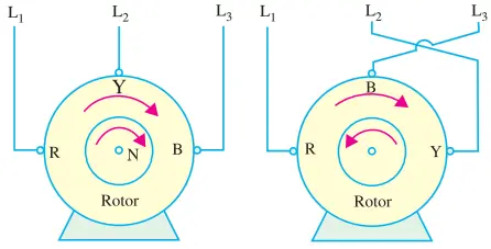
It reverses the direction of rotation of the synchronously-rotating magnetic field which produces a torque in the reverse direction, thus applying braking on the motor.
Hence, at the first instant after plugging, the rotor is running in a direction opposite to that of the stator field. It means that speed of the rotor relative to the magnetic field is (Ns + N) ≅ 2Ns as shown in Fig. 4. In Fig 4, ordinate BC represents the braking torque at the instant of plugging.
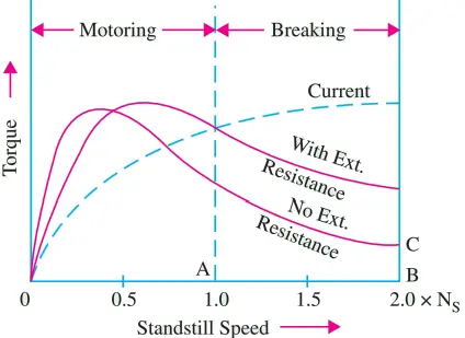
As seen, this torque gradually increases as motor approaches standstill condition after which motor is disconnected from the supply (otherwise it will start up again in the reverse direction).
As compared to squirrel cage motors, slip-ring motors are more suitable for plugging because, in their case, external resistance can be added to get the desired braking torque.
Rheostatic Braking of AC Motors
In this method of electric braking, motor is disconnected from the supply though its field continues to be energised in the same direction.
The motor starts working as a generator and all the kinetic energy of the equipment to be braked is converted into electrical energy and is further dissipated in the variable external resistance R connected across the motor during the braking period.
This external resistance must be less than the critical resistance otherwise there will not be enough current for generator excitation.
D.C. and synchronous motors can be braked this way but induction motors require separate d.c. source for field excitation.
This method has advantage over plugging because, in this case, no power is drawn from the supply during braking.
Rheostatic Braking of D.C. Motors
Fig. 5 shows connections for a d.c. shunt motor. For applying rheostatic braking armature is disconnected from the supply and connected to a variable external resistance R while the field remains on the supply.
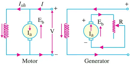
The motor starts working as a generator whose induced emf Eb depends upon its speed. At the start of braking, when speed is high, Eb is large, hence Ia is large. As speed decreases, Eb decreases, hence Ia decreases.
Since Tb ∝ Φ Ia , it will be high at high speeds but low at low speeds. By gradually cutting out R, Ia and, hence, TB can be kept constant throughout. Value of Ia = Eb (R + Ra).
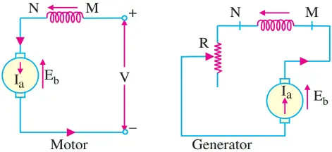
Fig. 6 shows running and braking conditions for a d.c. series motor. In this case also, for rheostatic braking, the armature is disconnected from the supply and, at the same time, is connected across R.
However, connections are so made that current keeps flowing through the series field in the same direction otherwise no braking torque would be produced. The motor starts working as a series generator provided R is less than the critical resistance.
Rheostatic Braking Torque
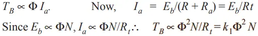
1. For D.C. shunt motors and synchronous motors, Φ is constant.
Hence TB = k1N.
2. In the case of series motors, flux depends on current. Hence, braking torque can be found from its magnetisation curve.
When rheostatic braking is to be applied to the series motors used for traction work, they are connected in parallel (Fig. 7) rather than in series because series connection produces excessive voltage across the loading rheostats.
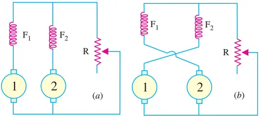
However, it is essential to achieve electrical stability in parallel operation of two series generators. It can be achieved either by equalizing the exciting currents i.e. by connecting the two fields in parallel [Fig. 7 (a)] or by cross-connection [Fig. 7 (b)] where field of one machine is excited by the armature current of the other.
If equalizer is not used, then the machine which happens to build up first will send current through the other in the opposite direction thereby exciting it with reverse voltage. Consequently, the two machines would be short-circuited upon themselves and may burn out on account of excessive voltage and, hence, current.
In the cross-connection of Fig. 7 (b), suppose the voltage of machine No. 1 is greater than that of No. 2. It would send a larger current through F2 thereby exciting it to a higher voltage. This results in stability of their parallel operation because stronger machine always helps the weaker one.
The cross-connection method has one special advantage over equalizer-connection method. If due to any reason (say, a run-back on a gradient) direction of rotation of the generators is reversed, no braking effect would be produced with connections of Fig. 7 (a) since the machines will fail to excite.
However, with cross-excited fields, the machines will build up in series and being short-circuited upon themselves, will provide an emergency braking and would not allow the coach/car to run back on a gradient.
Rheostatic Braking of Induction Motors
If an induction motor is disconnected from the supply for rheostatic braking, there would be no magnetic flux and, hence, no generated emf in the rotor and no braking torque.
However, if after disconnection, direct current is passed through the stator, steady flux would be set up in the air-gap which will induce current, in the short-circuited rotor.
This current which is proportional to the rotor speed, will produce the required braking torque whose value can be regulated by either controlling d.c. excitation or varying the rotor resistance.
Regenerative Braking
In this method of braking, motor is not disconnected from the supply but is made to run as a generator by utilizing the kinetic energy of the moving train. Electrical energy is fed back to the supply.
The magnetic drag produced on account of generator action offers the braking torque. It is the most efficient method of braking.
Take the case of a shunt motor. It will run as a generator whenever its Eb becomes greater than V. Now, Eb can exceed V in two ways:-
- by increasing field excitation
- by increasing motor speed beyond its normal value, field current remaining the same. It happens when load on the motor has overhauling characteristics as in the lowering of the cage or a hoist or the down-gradient movement of an electric train.
Regenerative braking can be easily applied to d.c. shunt motors though not down to very low speeds because it is not possible to increase field current sufficiently.
In the case of d.c. series motors, reversal of current necessary to produce regeneration would cause reversal of the field and hence of Eb.
Consequently, modifications are necessary if regenerative braking is to be employed with d.c. series motors used in electric traction. It may, however, be clearly understood that regenerative braking cannot be used for stopping a motor. Its main advantages are
- Reduced energy consumption particularly on main-line railways having long gradients and mountain railways.
- Reduced wear of brake shoes and wheel tyres.
- Lower maintenance cost for these items.
Advantages of Electrical Braking over Mechanical Braking
- In mechanical braking; due to excessive wear on brake drum, liner etc. it needs frequent and costly replacement. This is not needed in electrical braking and so electrical braking is more economical than mechanical braking.
- Due to wear and tear of brake liner frequent adjustments are needed thereby making the maintenance costly.
- Mechanical braking produces metal dust, which can damage bearings. Electrical braking has no such problems.
- If mechanical brakes are not correctly adjusted it may result in shock loading of machine or machine parts in case of lift, trains which may result in discomfort to the occupants.
- Electrical braking is smooth.
- In mechanical braking the heat is produced at brake liner or brake drum, which may be a source of failure of the brake. In electric braking the heat is produced at convenient place, which in no way is harmful to a braking system.
- In regenerative braking electrical energy can be returned back to the supply which is not possible in mechanical braking.
- Noise produced is very high in mechanical braking.
Only disadvantage in electrical braking is that it is ineffective in applying holding torque.
DC Motor Braking | MCQ
1. The most economical method of electric braking is
(a) plugging.
(b) dynamic braking with separate excitation.
(c) dynamic braking with self excitation.
(d) regenerative braking.
Answer: (d) regenerative braking.
2. The electric braking system employed with dc shunt motors, in which the armature connections are reversed so that the motor tends to run in opposite direction is called the …….. braking.
(a) plugging
(b) rheostatic
(d) dynamic
(d) regenerative
Answer: (a) plugging
3. Plugging of dc machine is normally executed by
(a) reversing the field polarity.
(b) reversing the armature polarity.
(c) reversing both field and armature polarity.
(d) connecting the resistance across armature terminals.
Answer: (b) reversing the armature polarity.
4. A dc shunt motor, running lightly at 1,000 rpm, is operated under plugging. With plugging connections left as it is the final speed of the motor will be
(a) zero.
(b) 1,000 rpm.
(c) —1,000 rpm.
(d) — 2,000 rpm.
Answer: (c) —1,000 rpm
5. In plugging of a dc shunt motor, the resistance is inserted in the armature circuit to
(a) increase the braking torque.
(b) stop the motor quickly.
(c) limit the armature current.
(d) have a shorting effect on the shunt field.
Answer: (c) limit the armature current.
6. The plugging provides …………. braking torque in comparison to rheostatic and regenerative braking systems.
(a) negligible
(b) small
(c) highest
Answer: (c) highest
7. The electric braking system commonly employed in rolling mills, elevators and printing presses is
(a) plugging.
(b) rheostatic.
(c) dynamic.
(d) regenerative.
Answer: (a) plugging.
8. The dynamic braking is generally used with ……… dc motors.
(a) series
(b) shunt
(c) compound
(d) all
Answer: (d) all
9. Dynamic braking is very effective if the dc motor
(a) is series excited.
(b) is shunt excited.
(c) is separately excited.
(d) has cumulative compound excitation.
Answer: (c) is separately excited.
10. For non-reversing dc drives it is preferable to use
(a) plugging.
(b) regenerative braking.
(c) dynamic braking with separate excitation.
(d) dynamic braking with self excitation.
Answer: (c) dynamic braking with separate excitation.
11. During rheostatic braking of dc series motors,
(a) the speed is reduced.
(b) the direction of rotation is reversed.
(c) the machine operates as a generator.
(d) none of the above.
Answer: (c) the machine operates as a generator.
12. During rheostatic braking the braking torque is proportional to
(a) speed.
(b) 1/speed.
(c) (speed)2.
Answer: (a) speed.
13. Regenerative braking is based on that the back emf is
(a) zero
(b) equal to applied voltage.
(c) less than applied voltage.
(d) more than applied voltage.
Answer: (d) more than applied voltage.
14. In regenerative braking, the motor energy is
(a) dissipated in armature heating.
(b) dissipated in windage losses.
(c) returned to the supply mains.
(d) none of the above.
Answer: (c) returned to the supply mains.
15. In case of dc shunt motors, the regenerative braking is employed when the load
(a) has an overhauling characteristic.
(b) is variable.
(c) is constant.
(d) also acts as a braking force.
(e) is constantly reducing.
Answer: (a) has an overhauling characteristic.
16. Regenerative braking
(a) can be easily applied to dc shunt motors.
(b) can be easily applied to dc series motors.
(c) can be used for stopping the motor.
(d) cannot be used when the load on motor has overhauling characteristics.
Answer: (a) can be easily applied to dc shunt motors.