AC Series Motor
If an ordinary d.c. series motor were connected to an a.c. supply, it will rotate and exert unidirectional torque because the current flowing both in the armature and field reverses at the same time. But the performance of such a motor will not be satisfactory for the following reasons:-
- The alternating flux would cause excessive eddy current loss in the yoke and field cores which will become extremely heated.
- Vicious sparking will occur at brushes because of the huge voltage and current induced in the short-circuited armature coils during their commutation period.
- Power factor is low because of high inductance of the field and armature circuits.
However, by proper modification of design and other refinements, a satisfactory single-phase motor, known as AC series motor, has been produced.
An A.C. series consists of a series field winding connected in series with the armature like a D. C. series motor. But in this motor, to reduce eddy current loss the entire iron structure of the field cores and yoke is laminated.
Power factor improvement is possible only by reducing the magnitudes of the reactances of the field and armature windings. Field reactance is reduced by reducing the number of turns on the field windings. For a given current, it will reduce the field m.m.f. which will result in reduced air-gap flux.
This will tend to increase the speed but reduce motor torque. To obtain the same torque, it will now be necessary to increase the number of armature turns proportionately. This will, however, result in increased inductive reactance of the armature, so that the overall reactance of the motor will not be significantly decreased.
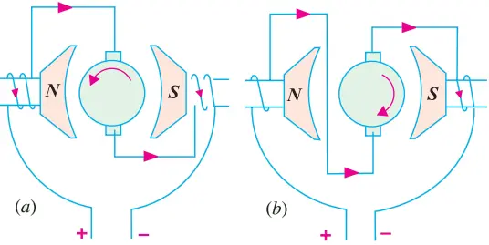
Increased armature m.m.f. can be neutralized effectively by using a compensating winding. In conductively-compensated motors, the compensating winding is connected in series with the armature [Fig. 1 (a)] whereas in inductively-compensated motors, the compensating winding is short-circuited and has no interconnection with the motor circuit [Fig. 1 (b)].
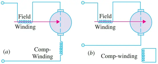
The compensating winding acts as a short-circuited secondary of a transformer, for which the armature winding acts as a primary. The current in the compensating winding will be proportional to the armature current and 180o out of phase with it.
Generally, all d.c. series motors are ‘provided’ with commutating poles for improving commutation (as in d.c. motors). But commutating poles alone will not produce satisfactory commutation, unless something is done to neutralize the huge voltage induced in the short-circuited armature coil by transformer action (this voltage is not there in d.c. series motor).
It should be noted that in an a.c. series motor, the flux produced by the field winding is alternating and it induces voltage (by transformer action) in the short-circuited armature coil during its commutating period. The field winding, associated with the armature coil undergoing commutation, acts as primary and the armature coil during its commutating period acts as a short-circuited secondary.
This transformer action produces heavy current in the armature coil as it passes through its commutating period and results in vicious sparking, unless the transformer voltage is neutralized.
One method, which is often used for large motors, consists of shunting the winding of each commutating pole with a non-inductive resistance, as shown in Fig. 2 (a).
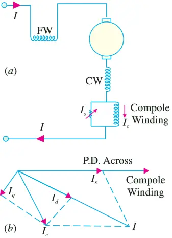
Fig. 2. (b) shows the vector diagram of a shunted commutator pole. The current Ic through the commutating pole (which lags the total motor current) can be resolved into two rectangular components Id and Iq as shown. Id produces a flux which is in phase with total motor current I whereas flux produced by Iq lags I by 90o.
By proper adjustment of shunt resistance (and hence Is), the speed voltage generated in a short-circuited coil by the cutting of the 90olagging component of the commutating pole flux may be made to neutralize the voltage induced by transformer action.
Universal Motor
A universal motor is defined as a motor which may be operated either on direct or single-phase a.c. supply at approximately the same speed and output.
In fact, it is a smaller version (5 to 150 W) of the a.c. series motor. Being a series-wound motor, it has high starting torque and a variable speed characteristic.
It runs at dangerously high speed on no-load. That is why such motors are usually built into the device they drive. Generally, universal motors are manufactured in two types:
- concentrated-pole, non-compensated type (low power rating)
- distributed-field compensated type (high power rating)
The non-compensated motor has two salient poles and is just like a 2-pole series d.c. motor except that whole of its magnetic path is laminated.
The laminated stator is necessary because the flux is alternating when motor is operated from a.c. supply. The armature is of wound type and similar to that of a small d.c. motor. It consists essentially of a laminated core having either straight or skewed slots and a commutator to which the leads of the armature winding are connected.
The distributed-field compensated type motor has a stator core similar to that of a split-phase motor and a wound armature similar to that of a small d.c. motor. The compensating winding is used to reduce the reactance voltage present in the armature when motor runs on a.c. supply. This voltage is caused by the alternating flux by transformer action.
In a 2-pole non-compensated motor, the voltage induced by transformer action in a coil during its commutation period is not sufficient to cause any serious commutation trouble. Moreover, high-resistance brushes are used to aid commutation.
(a) Operation. As explained above, such motors develop unidirectional torque, regardless of whether they operate on d.c. or a.c. supply. The production of unidirectional torque, when the motor runs on a.c. supply can be easily understood from Fig. 3.
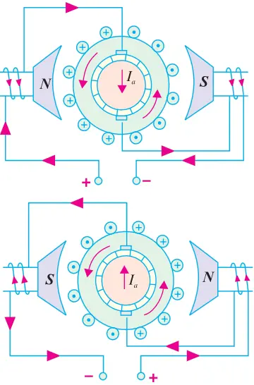
The motor works on the same principle as a d.c. motor i.e. force between the main pole flux and the current-carrying armature conductors. This is true regardless of whether the current is alternating or direct.
(b) Speed/Load Characteristic. The speed of a universal motor varies just like that of a d.c. series motor i.e. low at full-load and high on no-load (about 20,000 r.p.m. in some cases). In fact, on no-load the speed is limited only by its own friction and windage load.
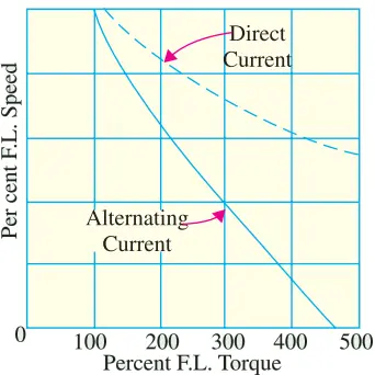
Fig. 4 shows typical torque characteristics of a universal motor both for d.c. and a.c. supply. Usually, gear trains are used to reduce the actual load speeds to proper values.
(c) Applications. Universal motors are used in vacuum cleaners where actual motor speed is the load speed. Other applications where motor speed is reduced by a gear train are:- drink and food mixers, portable drills and domestic sewing machine etc.
(d) Reversal of Rotation. The concentrated-pole (or salient-pole) type universal motor may be reversed by reversing the flow of current through either the armature or field windings. The usual method is to interchange the leads on the brush holders (Fig. 5).
The distributed-field compensated type universal motor may be reversed by interchanging either the armature or field leads and shifting the brushes against the direction in which the motor will rotate. The extent of brush shift usually amounts to several commutator bars.
Speed Control of Universal Motors
The following methods are usually employed for speed-control purposes:-
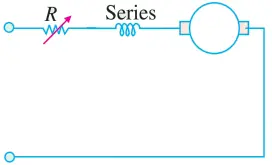
(i) Resistance Method. As shown in Fig. 6, the motor speed is controlled by connecting a variable resistance R in series with the motor. This method is employed for motors used in sewing machines. The amount of resistance in the circuit is changed by means of a foot-pedal.
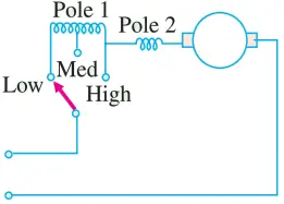
(ii) Tapping-field Method. In this method, a field pole is tapped at various points and speed is controlled by varying the field strength (Fig. 7). For this purpose, either of the following two arrangements may be used:-
- The field pole is wound in various sections with different sizes of wire and taps are brought out from each section.
- Nichrome resistance wire is wound over one field pole and taps are brought out from this wire.
(iii) Centrifugal Mechanism. Universal motors, particularly those used for home food and drink mixers, have a number of speeds. Selection is made by a centrifugal device located inside the motor and connected, as shown in Fig. 8. The switch is adjustable by means of an external lever.
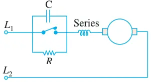
If the motor speed rises above that set by the lever, the centrifugal device opens two contacts and inserts resistance R in the circuit, which causes the motor speed to decrease.
When motor runs slow, the two contacts close and short-circuit the resistance, so that the motor speed rises. This process is repeated so rapidly that variations in speed are not noticeable.
The resistance R is connected across the governor points as shown in Fig. 8.
A capacitor C is used across the contact points in order to reduce sparking produced due to the opening and closing of these points. Moreover, it prevents the pitting of contacts.