Types of Functional Relays
Most of the relays in service on power system today operate on the principle of electromagnetic attraction or electromagnetic induction. Regardless of the principle involved, relays are generally classified according to the function they are called upon to perform in the protection of electric power circuits.
For example, a relay which recognises overcurrent in a circuit (i.e. current greater than that which can be tolerated) and initiates corrective measures would be termed as an overcurrent relay irrespective of the relay design.
Similarly an overvoltage relay is one which recognises overvoltage in a circuit and initiates the corrective measures. Although there are several types of special function relays, only the following important types will be discussed in this article:-
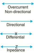
(1) Induction type overcurrent relays
(2) Induction type reverse power relays
(3) Distance relays
(4) Differential relays
(5) Translay scheme
Induction Type Overcurrent Relay (non-directional)
This type of relay works on the induction principle and initiates corrective measures when current in the circuit exceeds the predetermined value. The actuating source is a current in the circuit supplied to the relay from a current transformer. These relays are used on a.c. circuits only and can operate for fault current flow in either direction.
Constructional details. Fig. 1 shows the important constructional details of a typical non-directional induction type overcurrent relay. It consists of a metallic (aluminium) disc which is free to rotate in between the poles of two electromagnets.
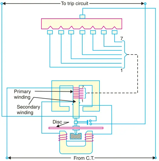
The upper electromagnet has a primary and a secondary winding. The primary is connected to the secondary of a C.T. in the line to be protected and is tapped at intervals. The tappings are connected to a plug-setting bridge by which the number of active turns on the relay operating coil can be varied, thereby giving the desired current setting.
The secondary winding is energised by induction from primary and is connected in series with the winding on the lower magnet.
The controlling torque is provided by a spiral spring. The spindle of the disc carries a moving contact which bridges two fixed contacts (connected to trip circuit) when the disc rotates through a pre-set angle.
This angle can be adjusted to any value between 0o and 360o. By adjusting this angle, the travel of the moving contact can be adjusted and hence the relay can be given any desired time setting.
Operation. The driving torque on the aluminium disc is set up due to the induction principle. This torque is opposed by the restraining torque provided by the spring.
Under normal operating conditions, restraining torque is greater than the driving torque produced by the relay coil current. Therefore, the aluminium disc remains stationary.
However, if the current in the protected circuit exceeds the pre-set value, the driving torque becomes greater than the restraining torque.
Consequently, the disc rotates and the moving contact bridges the fixed contacts when the disc has rotated through a pre-set angle. The trip circuit operates the circuit breaker which isolates the faulty section.
Induction Type Directional Power Relay
This type of relay operates when power in the circuit flows in a specific direction. Unlike a non-directional overcurrent relay, a directional power relay is so designed that it obtains its operating torque by the interaction of magnetic fields derived from both voltage and current source of the circuit it protects.
Thus this type of relay is essentially a wattmeter and the direction of the torque set up in the relay depends upon the direction of the current relative to the voltage with which it is associated.
Constructional details. Fig. 2 shows the essential parts of a typical induction type directional power relay. It consists of an aluminum disc which is free to rotate in between the poles of two electromagnets.
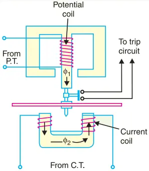
The upper electromagnet carries a winding (called potential coil) on the central limb which is connected through a potential transformer (P.T.) to the circuit voltage source. The lower electromagnet has a separate winding (called current coil) connected to the secondary of C.T. in the line to be protected.
The current coil is provided with a number of tappings connected to the plug-setting bridge (not shown in Fig. for clarity). This permits to have any desired current setting. The restraining torque is provided by a spiral spring.
The spindle of the disc carries a moving contact which bridges two fixed contacts when the disc has rotated through a pre-set angle. By adjusting this angle, the travel of the moving disc can be adjusted and hence any desired time-setting can be given to the relay.
Operation. The flux φ1 due to current in the potential coil will be nearly 90o lagging behind the applied voltage V. The flux φ2 due to current coil will be nearly in phase with the operating current I [See vector diagram in Fig. 3].
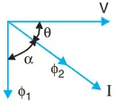
The interaction of fluxes φ1 and φ2 with the eddy currents induced in the disc produces a driving torque proportional to power in the circuit and the direction of driving torque on the disc depends upon the direction of power flow in the circuit to which the relay is associated.
When the power in the circuit flows in the normal direction, the driving torque and the restraining torque (due to spring) help each other to turn away the moving contact from the fixed contacts. Consequently, the relay remains inoperative.
However, the reversal of current in the circuit reverses the direction of driving torque on the disc. When the reversed driving torque is large enough, the disc rotates in the reverse direction and the moving contact closes the trip circuit. This causes the operation of the circuit breaker which disconnects the faulty section.
Induction Type Directional Overcurrent Relay
The directional power relay discussed above is unsuitable for use as a directional protective relay under short-circuit conditions. When a short-circuit occurs, the system voltage falls to a low value and there may be insufficient torque developed in the relay to cause its operation.
This difficulty is overcome in the directional overcurrent relay which is designed to be almost independent of system voltage and power factor.
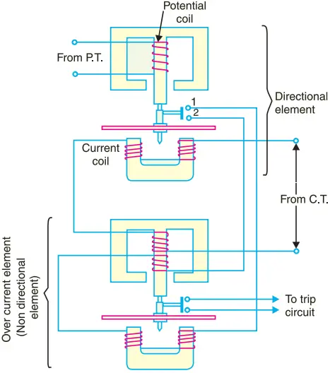
Constructional details. Fig. 4 shows the constructional details of a typical induction type directional ovecurrent relay. It consists of two relay elements mounted on a common case viz.
(i) directional element and (ii) non-directional element.
(i) Directional element. It is essentially a directional power relay which operates when power flows in a specific direction. The potential coil of this element is connected through a potential transformer (P.T.) to the system voltage.
The current coil of the element is energised through a C.T. by the circuit current. This winding is carried over the upper magnet of the non-directional element. The trip contacts (1 and 2) of the directional element are connected in series with the secondary circuit of the overcurrent element. Therefore, the latter element cannot start to operate until its secondary circuit is completed.
In other words, the directional element must operate first (i.e. contacts 1 and 2 should close) in order to operate the overcurrent element.
(ii) Non-directional element. It is an overcurrent element similar in all respects to an Induction Type Overcurrent Relay (non-directional) described above.
The spindle of the disc of this element carries a moving contact which closes the fixed contacts (trip circuit contacts) after the operation of directional element.
It may be noted that plug-setting bridge is also provided in the relay for current setting but has been omitted in the figure for clarity and simplicity. The tappings are provided on the upper magnet of overcurrent element and are connected to the bridge.
Operation. Under normal operating conditions, power flows in the normal direction in the circuit protected by the relay. Therefore, directional power relay (upper element) does not operate, thereby keeping the overcurrent element (lower element) unenergised.
However, when a short-circuit occurs, there is a tendency for the current or power to flow in the reverse direction. Should this happen, the disc of the upper element rotates to bridge the fixed contacts 1 and 2.
This completes the circuit for overcurrent element. The disc of this element rotates and the moving contact attached to it closes the trip circuit. This operates the circuit breaker which isolates the faulty section.
The two relay elements are so arranged that final tripping of the current controlled by them is not made till the following conditions are satisfied:-
- current flows in a direction such as to operate the directional element.
- current in the reverse direction exceeds the pre-set value.
- excessive current persists for a period corresponding to the time setting of overcurrent element.
Distance or Impedance Relays
The operation of the relays discusssed so far depended upon the magnitude of current or power in the protected circuit. However, there is another group of relays in which the operation is governed by the ratio of applied voltage to current in the protected circuit. Such relays are called distance or impedance relays because impedance is an electrical measure of distance along a transmission line.
In an impedance relay, the torque produced by a current element is opposed by the torque produced by a voltage element. The relay will operate when the ratio V/I is less than a predetermined value.
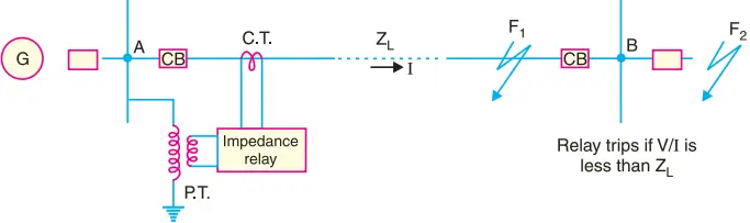
Fig. 5 illustrates the basic principle of operation of an impedance relay. The voltage element of the relay is excited through a potential transformer (P.T.) from the line to be protected. The current element of the relay is excited from a current transformer (C.T.) in series with the line. The portion AB of the line is the protected zone.
Under normal operating conditions, the impedance of the protected zone is ZL. The relay is so designed that it closes its contacts whenever impedance of the protected section falls below the pre-determined value i.e. ZL in this case.
Now suppose a fault occurs at point F1 in the protected zone. The impedance Z (= V/I) between the point where the relay is installed and the point of fault will be less than ZL and hence the relay operates.
Should the fault occur beyond the protected zone (say point F2), the impedance Z will be greater than ZL and the relay does not operate.
Types. A distance or impedance relay is essentially an ohmmeter and operates whenever the impedance of the protected zone falls below a pre-determined value. There are two types of distance relays in use for the protection of power supply, namely;
- Definite-distance relay which operates instantaneously for fault upto a pre-determined distance from the relay.
- Time-distance relay in which the time of operation is proportional to the distance of fault from the relay point. A fault nearer to the relay will operate it earlier than a fault farther away from the relay.
It may be added here that the distance relays are produced by modifying either of two types of basic relays; the balance beam or the induction disc.
Definite – Distance Type Impedance Relay
Fig. 6 shows the schematic arrangement of a definite-distance type impedance relay.
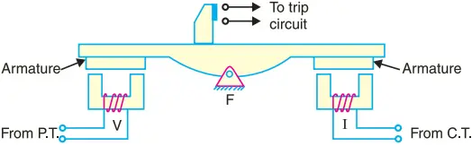
It consists of a pivoted beam F and two electromagnets energised respectively by a current and voltage transformer in the protected circuit.
The armatures of the two electromagnets are mechanically coupled to the beam on the opposite sides of the fulcrum. The beam is provided with a bridging piece for the trip contacts. The relay is so designed that the torques produced by the two electromagnets are in the opposite direction.
Operation. Under normal operating conditions, the pull due to the voltage element is greater than that of the current element. Therefore, the relay contacts remain open.
However, when a fault occurs in the protected zone, the applied voltage to the relay decreases whereas the current increases. The ratio of voltage to current (i.e. impedance) falls below the pre-determined value.
Therefore, the pull of the current element will exceed that due to the voltage element and this causes the beam to tilt in a direction to close the trip contacts. By providing tappings on the coils, the setting value of the relay can be changed.
Time-Distance Impedance Relay
A time-distance impedance relay is one which automatically adjusts its operating time according to the distance of the relay from the fault point i.e.
Operating time, T ∝ V/I ∝ Z ∝ distance
Construction. Fig. 7 shows the schematic arrangement of a typical induction type time-distance impedance relay. It consists of a current driven induction element similar to the double-winding type induction overcurrent relay.
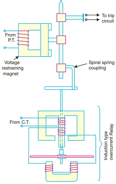
The spindle carrying the disc of this element is connected by means of a spiral spring coupling to a second spindle which carries the bridging piece of the relay trip contacts. The bridge is normally held in the open position by an armature held against the pole face of an electromagnet excited by the voltage of the circuit to be protected.
Operation. Under normal load conditions, the pull of the armature is more than that of the induction element and hence the trip circuit contacts remain open. However, on the occurrence of a short-circuit, the disc of the induction current element starts to rotate at a speed depending upon the operating current.
As the rotation of the disc proceeds, the spiral spring coupling is wound up till the tension of the spring is sufficient to pull the armature away from the pole face of the voltage-excited magnet.
Immediately this occurs, the spindle carrying the armature and bridging piece moves rapidly in response to the tension of the spring and trip contacts are closed. This opens the circuit breaker to isolate the faulty section. The speed of rotation of the disc is approximately proportional to the operating current, neglecting the effect of control spring.
Also the time of operation of the relay is directly proportional to the pull of the voltage-excited magnet and hence to the line voltage V at the point where the relay is connected. Therefore, the time of operation of relay would vary as V/I i.e. as Z or distance.
Differential Relays
Most of the relays discussed so far relied on excess of current for their operation. Such relays are less sensitive because they cannot make correct distinction between heavy load conditions and minor fault conditions. In order to overcome this difficulty, differential relays are used.
A differential relay is one that operates when the phasor difference of two or more similar electrical quantities exceeds a pre-determined value. Thus a current differential relay is one that compares the current entering a section of the system with the current leaving the section.
Under normal operating conditions, the two currents are equal but as soon as a fault occurs, this condition no longer applies. The difference between the incoming and outgoing currents is arranged to flow through the operating coil of the relay.
If this differential current is equal to or greater than the pickup value, the relay will operate and open the circuit breaker to isolate the faulty section.
It may be noted that almost any type of relay when connected in a particular way can be made to operate as a differential relay.
In other words, it is not so much the relay construction as the way the relay is connected in a circuit that makes it a differential relay.
There are two fundamental systems of differential or balanced protection viz.
- Current balance protection
- Voltage balance protection
Current Differential Relay
Fig. 8 shows an arrangement of an overcurrent relay connected to operate as a differential relay.
A pair of identical current transformers are fitted on either end of the section to be protected (alternator winding in this case). The secondaries of CT’s are connected in series in such a way that they carry the induced currents in the same direction. The operating coil of the overcurrent relay is connected across the CT secondary circuit. This differential relay compares the current at the two ends of the alternator winding.
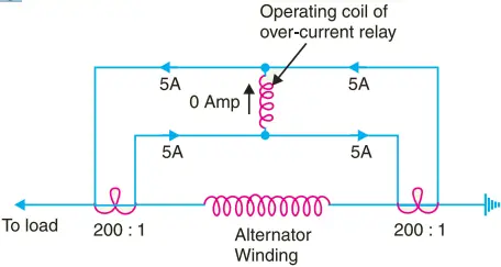
Under normal operating conditions, suppose the alternator winding carries a normal current of 1000 A. Then the currents in the two secondaries of CT’s are equal [See Fig. 8]. These currents will merely circulate between the two CT’s and no current will flow through the differential relay. Therefore, the relay remains inoperative.
If a ground fault occurs on the alternator winding, the two secondary currents will not be equal and the current flows through the operating coil of the relay, causing the relay to operate. The amount of current flow through the relay will depend upon the way the fault is being fed.
Disadvantages:-
- The impedance of the pilot cables generally causes a slight difference between the currents at the two ends of the section to be protected. If the relay is very sensitive, then the small differential current flowing through the relay may cause it to operate even under no fault conditions.
- Pilot cable capacitance causes incorrect operation of the relay when a large through-current flows.
- Accurate matching of current transformers cannot be achieved due to pilot circuit impedance.
The above disadvantages are overcome to a great extent in biased beam relay.
Biased Beam Relay. The biased beam relay (also called percentage differential relay) is designed to respond to the differential current in terms of its fractional relation to the current flowing through the protected section.
Fig. 9 shows the schematic arrangement of a biased beam relay. It is essentially an overcurrent balanced beam relay type with an additional restraining coil. The restraining coil produces a bias force in the opposite direction to the operating force.
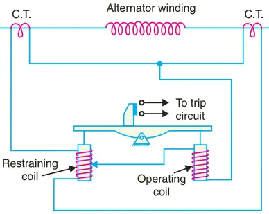
Under normal and through load conditions, the bias force due to restraining coil is greater than the operating force. Therefore, the relay remains inoperative.
When an internal fault occurs, the operating force exceeds the bias force. Consequently, the trip contacts are closed to open the circuit breaker. The bias force can be adjusted by varying the number of turns on the restraining coil.
The equivalent circuit of a biased beam relay is shown in Fig. 10. The differential current in the operating coil is proportional to i2 − i1 and the equivalent current in the restraining coil is proportional to (i 1 + i 2)/2 since the operating coil is connected to the mid-point of the restraining coil.
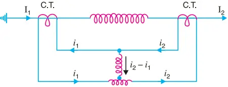
It is clear that greater the current flowing through the restraining coil, the higher the value of current required in the operating winding to trip the relay.
Thus under a heavy load, a greater differential current through the relay operating coil is required for operation than under light load conditions.
This relay is called percentage relay because the operating current required to trip can be expressed as a percentage of load current.
Voltage Balance Differential Relay
Fig. 11 shows the arrangement of voltage balance protection. In this scheme of protection, two similar current transformers are connected at either end of the element to be protected (e.g. an alternator winding) by means of pilot wires.
The secondaries of current transformers are connected in series with a relay in such a way that under normal conditions, their induced e.m.f.s’ are in opposition.
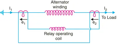
Under healthy conditions, equal currents (I1 = I2) flow in both primary windings. Therefore, the secondary voltages of the two transformers are balanced against each other and no current will flow through the relay operating coil.
When a fault occurs in the protected zone, the currents in the two primaries will differ from one another (i.e. I1 ≠ I2) and their secondary voltages will no longer be in balance.
This voltage †difference will cause a current to flow through the operating coil of the relay which closes the trip circuit.
Disadvantages: The voltage balance system suffers from the following drawbacks:-
- A multi-gap transformer construction is required to achieve the accurate balance between current transformer pairs.
- The system is suitable for protection of cables of relatively short lengths due to the capacitance of pilot wires. On long cables, the charging current may be sufficient to operate the relay even if a perfect balance of current transformers is attained.
The above disadvantages have been overcome in Translay (modified) balanced voltage system.
Translay System
This system is the modified form of voltage-balance system. Although the principle of balanced (opposed) voltages is retained, it differs from the above voltage-balance system in that the balance or opposition is between voltages induced in the secondary coils wound on the relay magnets and not between the secondary voltages of the line current transformers.
Since the current transformers used with Translay scheme have only to supply to a relay coil, they can be made of normal design without any air gaps. This permits the scheme to be used for feeders of any voltage.
Constructional details. Fig. 12 shows the simplified diagram illustrating the principle of Translay scheme. It consists of two identical double winding induction type relays fitted at either end of the feeder to be protected.
The primary circuits (11, 11a) of these relays are supplied through a pair of current transformers. The secondary windings (12, 13 and 12a, 13a) of the two relays are connected in series by pilot wires in such a way that voltages induced in the former opposes the other.
The compensating devices (18, 18a) neutralise the effects of pilot-wire capacitance currents and of inherent lack of balance between the two current transformers.
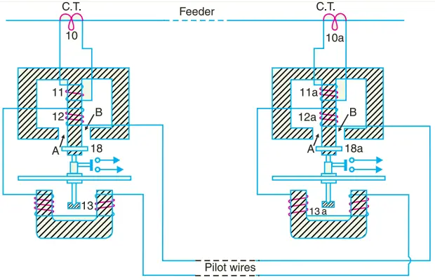
Operation. Under healthy conditions, current at the two ends of the protected feeder is the same and the primary windings (11, 11a) of the relays carry the same current. The windings 11 and 11a induce equal e.m.f.s in the secondary windings 12, 12a and 13, 13a.
As these windings are so connected that their induced voltages are in opposition, no current will flow through the pilots or operating coils and hence no torque will be exerted on the disc of either relay.
In the event of fault on the protected feeder, current leaving the feeder will differ from the current entering the feeder. Consequently, unequal voltages will be induced in the secondary windings of the relays and current will circulate between the two windings, causing the torque to be exerted on the disc of each relay.
As the direction of secondary current will be opposite in the two relays, therefore, the torque in one relay will tend to close the trip circuit while in the other relay, the torque will hold the movement in the normal un-operated position.
It may be noted that resulting operating torque depends upon the position and nature of the fault in the protected zone and at least one element of either relay will operate under any fault condition.
It is worthwhile here to mention the role of closed copper rings (18, 18a) in neutralising the effects of pilot capacitive currents. Capacitive currents lead the voltage impressed across the pilots by 90o and when they flow in the operating winding 13 and 13a (which are of low inductance), they produce fluxes that also lead the pilot voltage by 90o.
Since pilot voltage is that induced in the secondary windings 12 and 12a, it lags by a substantial angle behind the fluxes in the field magnet air gaps A and B. The closed copper rings (18, 18a) are so adjusted that this angle is approximately 90o. In this way fluxes acting on the disc are in phase and hence no torque is exerted on the relay disc.