Coriolis Flowmeters
Coriolis flowmeters are incredibly versatile and accurate, but their internal operation can be difficult to understand.
Put into very simple terms, a Coriolis flowmeter works by shaking one or more tubes carrying the flowing fluid, then precisely measuring the frequency and phase of that shaking.
The back-and-forth shaking is driven by an electromagnetic coil, powered by an electronic amplifier circuit to shake the tube(s) at their mechanical resonant frequency.
Since this frequency depends on the mass of each tube, and the mass of the tubes depends on the density of the fluid filling the fixed volume of the tubes, the resonant frequency becomes an inverse indication of fluid density regardless of fluid flow through the tubes.
As fluid begins to move through the tubes, the inertia of the moving fluid adds another dimension to the tubes’ motion: the tubes begin to undulate, twisting slightly instead of just shaking back and forth.
This twisting motion is directly proportional to the mass flow rate, and is internally measured by comparing the phase shift (θ) between motion at one point on the tube versus another point on the tube: the greater the undulation, the greater the phase shift between these two points’ vibrations. Expressed as proportionalities:
Tube frequency ∝ 1/Density or f ∝ 1/ρ
Tube twisting ∝ Mass flowrate or θ ∝ W
Coriolis Flowmeter Construction
A common Coriolis flowmeter design uses a Ushaped tube that redirects the fluid flow back to the center of rotation. The curved end of the flexible U-tube is forced to shake back and forth by an electromagnetic force coil (like the force coil on an audio speaker) while the tube ends anchor to a stationary manifold:
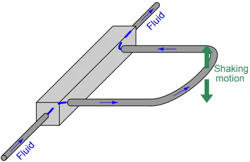
If fluid inside the tube is stagnant (no flow), the tube will simply vibrate back and forth with the applied force.
However, if fluid flows through the tube, the moving fluid molecules will experience acceleration as they travel from the anchored base to the tube’s rounded end, then experience deceleration as they travel back to the anchored base.
This continual acceleration and subsequent deceleration of new mass generates a Coriolis force altering the tube’s motion.
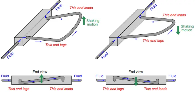
This Coriolis force causes the U-tube assembly to twist. The tube portion carrying fluid from the anchored base to the end tends to lag in motion because the fluid molecules in that section of the tube are being accelerated to a greater lateral velocity.
The tube portion carrying fluid from the end back to the anchored base tends to lead in motion because those molecules are being decelerated back to zero lateral velocity. As mass flow rate through the tube increases, so does the degree of twisting.
By monitoring the severity of this twisting motion, we may infer the mass flow rate of the fluid passing through the tube:
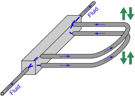
In order to reduce the amount of vibration generated by a Coriolis flowmeter, and more importantly to reduce the effect any external vibrations may have on the flowmeter, two identical Utubes are built next to each other and shaken in complementary fashion (always moving in opposite directions).
Tube twist is measured as relative motion from one tube to the next, not as motion between the tube and the stationary housing of the flowmeter. This (ideally) eliminates the effect of any common-mode vibrations on the inferred flow measurement:
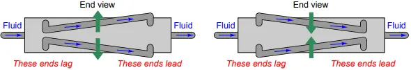
Viewed from the end, the complimentary shaking and twisting of the tubes looks like this:
Great care is taken by the manufacturer to ensure the two tubes are as close to identical as possible: not only are their physical characteristics precisely matched, but the fluid flow is split very evenly between the tubes69 so their respective Coriolis forces should be identical in magnitude.
A photograph of a Rosemount (Micro-Motion) U-tube Coriolis flowmeter demonstration unit shows the U-shaped tubes (one tube is directly above the other in this picture, so you cannot tell there are actually two U-tubes):
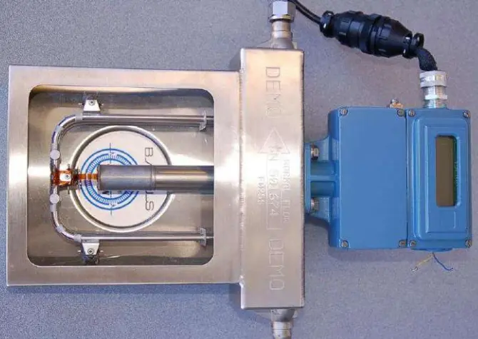
A closer inspection of this flowmeter shows that there are actually two U-tubes, one positioned directly above the other, shaken in complementary directions by a common electromagnetic force coil:
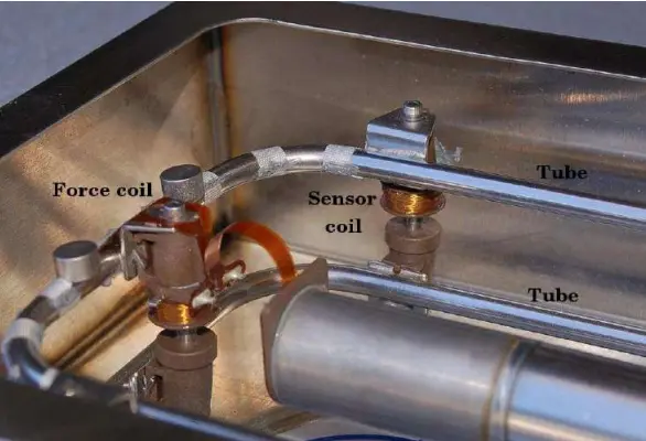
The force coil works on the same principle as an audio speaker: AC electric current passed through a wire coil generates an oscillating magnetic field, which acts against a permanent magnet’s field to produce an oscillating force. In the case of an audio speaker, this force causes a lightweight cone to move, which then creates sound waves through the air.
In the case of the Coriolis meter assembly, the force pushes and pulls between the two metal tubes, causing them to alternately separate and come together (shake in opposite directions).
Two magnetic displacement sensors monitor the relative motions of the tubes and transmit signals to an electronics module for digital processing.
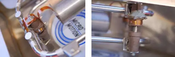
One of those sensor coils may be seen in the previous photograph. Both the force coil and the sensor coil are nothing more than permanent magnets surrounded by movable copper wire coils.
The main difference between the force coil and the sensor coil is that the force coil is powered by an AC electric current to impart a vibratory force to the tubes, whereas the sensor coils are both unpowered so they can detect tube motion by generating AC voltage signals to be sensed by the electronics module. The force coil is shown in the left-hand photograph, while one of the two sensor coils appears in the right-hand photograph:
The two AC signals generated by the sensor coils provide data from which the electronics package may interpret fluid density and mass flow rate. The frequency of the two coils’ signals is inversely related to fluid density, because a denser fluid will cause the tubes to have greater mass and therefore vibrate at a lower frequency.
The phase shift of the two coils’ signals is directly related to mass flow rate, because a greater mass flow rate will cause the tubes to twist to a greater degree, causing the sensors’ signals to shift further out of phase with each other.
Advances in sensor technology and signal processing have allowed the construction of Coriolis flowmeters employing straighter tubes than the U-tube unit previously illustrated and photographed. Straighter tubes are advantageous for reasons of reduced plugging potential and the ability to easily drain all liquids out of the flowmeter when needed.
In straight-tube Coriolis flowmeters, we still find the same general design of a force coil flanked by matching sensor coils measuring vibration frequency (for density measurement) and phase shift (for mass flow measurement).
Matched Tubes and Electronics
The tubes inside a Coriolis flowmeter are not just conduits for fluid flow, they are also precision spring elements and volume chambers.
As such, it is important to precisely know the spring characteristics and precise dimensions of these tubes so both mass flow and density may be inferred from tube motion.
Every Coriolis flow element is factory-tested to determine the flow tubes’ mechanical properties, then the electronic transmitter is programmed with these parameters describing the tubes’ mechanical properties.
The following photograph shows a close-up view of the nameplate on a Rosemount (Micro-Motion) Coriolis mass flowmeter, showing the physical constant values determined for that specific flowtube assembly at the time of manufacture:
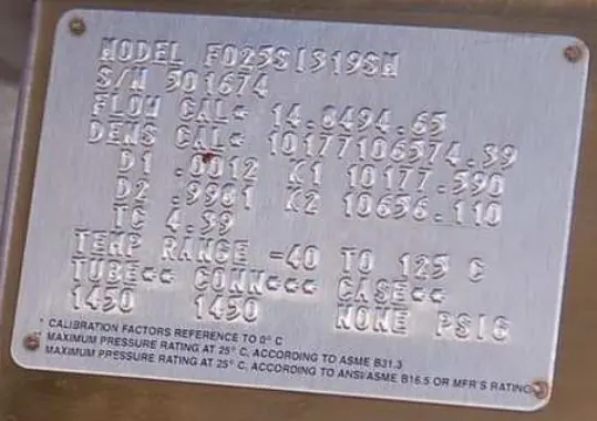
This means every Coriolis flowmeter element (the tube and sensor assembly) is unique, with no two identical in behavior. Consequently, the transmitter (the electronics package outputting the process variable signals) must be programmed with values describing the element’s behavior, and the complete flowmeter is shipped from the manufacturer as a matched set.
You cannot interchange elements and transmitters without re-programming the transmitters with the new elements’ physical constant values.
Density and Temperature Measurement
The tubes within a Coriolis flowmeter are shaken at their mechanical resonant frequency to maximize their shaking motion while minimizing electrical power applied to the force coil. The electronics module uses a feedback loop between the sensor coils and the shaker coil to maintain the tubes in a continuous state of resonant oscillation.
This resonant frequency changes with process fluid density, since the effective mass of the fluid-filled tubes changes with process fluid density, and mass is one of the variables influencing the mechanical resonant frequency of any elastic structure.
Note the “mass” term in the following formula, describing the resonant frequency of a tensed string:
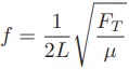
Where, f = fundamental resonant frequency of string (Hertz), L = string length (meters), FT = string tension (newtons) µ = unit mass of string (kilograms per meter).
A fluid-filled tube is a close analogue to a tensed string, with tube stiffness analogous to string tension and liquid density analogous to unit mass.
So long as the spring constant (tube stiffness) is known, the resonant frequency of the tubes’ vibration serves to indicate the unit mass of the tubes, which in turn represents fluid density given the known internal volume of the tubes.
Temperature changes have the potential to interfere with this density measurement, because temperature affects the elasticity of metal (Young’s modulus) as well as the tubes’ physical dimensions.
This is why all Coriolis flowmeters are equipped with RTD temperature sensors to continuously monitor the temperature of the vibrating tubes.
The flowmeter’s microprocessor takes this tube temperature measurement and uses it to compensate for the resulting elasticity and dimensional changes based on a prior modeling of the tube metal characteristics.
In other words, the flowmeter’s microprocessor continuously updates the force variable (FT ) representing tube stiffness in the resonant frequency equation so that the frequency will always be a reliable indicator of unit mass (fluid density).
This temperature measurement happens to be accessible as an auxiliary output signal, which means a Coriolis flowmeter may double as a (very expensive!) temperature transmitter in addition to measuring mass flow rate and fluid density.
The ability to simultaneously measure three process variables (mass flow rate, temperature, and density) makes the Coriolis flowmeter a very versatile instrument indeed.
This is especially true when the flowmeter in question communicates digitally using a “fieldbus” standard rather than an analog 4-20 mA signal.
Fieldbus communication allows multiple variables to be transmitted by the device to the host system (and/or to other devices on the same fieldbus network), allowing the Coriolis flowmeter to do the job of three instruments!
Proper Installation
Although Coriolis flowmeters are immune to fluid turbulence and therefore have no upstream or downstream straight-pipe length requirements, they are still susceptible to other installation-related problems.
One of these is vibration: attaching a Coriolis flowmeter a machine that vibrates, or to piping that vibrates from attachment to such a machine, can be problematic because sufficient external vibration may interfere with the resonant vibration of the flowmeter tubes, causing errors in density and/or flow measurement.
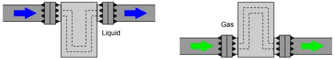
A problem unique to bent-tube Coriolis flowmeters is the entrapment of gas bubbles (in a liquid process) or liquid droplets (in a gas process).
Either condition will create an uneven distribution of mass inside the flowmeter’s tubes, potentially leading to measurement errors in density and/or flow. The bent tubes of a Coriolis flowmeter should be oriented such that bubbles or droplets cannot collect within them, similar to how a differential pressure sensor should be oriented in realtion to an orifice plate: for liquid processes, the bent tubes should be located below the pipe’s centerline; for gas processes, the bent tubes should be located above the pipe’s centerline:
Capabilities and Limitations of Coriolis Flowmeter
Even though a Coriolis flowmeter inherently measures mass flow rate, the continuous measurement of fluid density allows the meter to calculate volumetric flow rate if this is the preferred means of expressing fluid flow.
The relationship between mass flow (W), volumetric flow (Q), and mass density (ρ) is quite simple: W = ρQ or Q = W/ρ
All the flowmeter’s computer must do to output a volumetric flow measurement is take the mass flow measurement value and divide that by the fluid’s measured density.
A simple exercise in dimensional analysis (performed with metric units of measurement) validates this concept for both forms of the equation shown above:
[kg/s ] = [kg/m3] [m3/s]
[m3/s] = [kg/s] ÷ [kg/m3]
Coriolis mass flowmeters are very accurate and dependable. They are also completely immune to swirl and other fluid disturbances, which means they may be located nearly anywhere in a piping system with no need at all for straight-run pipe lengths upstream or downstream of the meter.
Their natural ability to measure true mass flow, along with their characteristic linearity and accuracy, makes them ideally suited for custody transfer applications (where the flow of fluid represents product being bought and sold).
Perhaps the greatest disadvantage of Coriolis flowmeters is their high initial cost, especially for large pipe sizes. Coriolis flowmeters are also more limited in operating temperature than other types of flowmeters and may have difficulty measuring low-density fluids (gases) and mixed-phase (liquid/vapor) flows.
The bent tubes used to sense process flow may also trap process fluid inside to the point where it becomes unacceptable for hygienic (e.g. food processing, pharmaceuticals) applications.
Straight-tube Coriolis flowmeter designs, and designs where the angle of the tubes is slight, fare better in this regard than the traditional U-tube Coriolis flowmeter design.
However, a disadvantage of straight tubes is that they are stiffer than U-shaped tubes, and so straight-tube Coriolis flowmeters tend to be less sensitive to low flow rates than their U-tube counterparts.