Protection of Transmission lines by Ground Wires
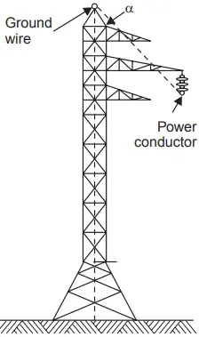
The ground wire is a conductor running parallel to the power conductors of the transmission line and is placed at the top of the tower structure supporting the power conductors (Fig. 1).
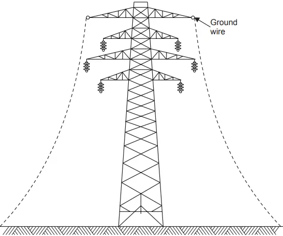
For the horizontal configuration of the power line conductors, there are two ground wires to provide effective shielding to power conductors from direct lightning stroke whereas in the vertical configuration, there is one ground wire.
The ground wire is made of galvanized steel wire or in the modern high voltage transmission lines ACSR conductor of the same size as the power conductor is used. The material and size of the conductor are more from mechanical consideration rather than electrical. A reduction in the effective ground resistance can be achieved by other relatively simpler and cheaper means. The ground wire serves the following purposes:
- It shields the power conductors from direct lightning strokes.
- Whenever a lightning stroke falls on the tower, the ground wires on both sides of the tower provide parallel paths for the stroke, thereby the effective impedance (surge impedance) is reduced and the tower top potential is relatively less.
- There is electric and magnetic coupling between the ground wire and the power conductors, thereby the chances of insulation failure are reduced.
The protective angle of the ground wire is defined as the angle between the vertical line passing through the ground wire and the line passing through the outermost power conductor (Fig. 1) and the protective zone is the zone which is a cone with apex at the location of the ground wire and surface generated by line passing through the outermost conductor.
According to Lacey, a ground wire provides adequate shielding to any power conductor that lies below a quarter circle drawn with its center at the height of the ground wire and with its radius equal to the height of the ground wire above the ground. If two or more ground wires are used, the protective zone between the two adjacent wires can be taken as a semi-circle having as its diameter a line connecting the two ground wires (Fig. 2).
The field experience along with laboratory investigation has proved that the protective angle should be almost 30° in plain areas whereas the angle decreases in hilly areas by an amount equal to the slope of the hill. The voltage to which a transmission tower is raised when lightning strikes the tower is independent of the operating voltage of the system and hence the design of the transmission line against lightning for a desired performance is independent of the operating voltage.
The basic requirements for the design of a line based on direct stroke are:
- The ground wires used for shielding the line should be mechanically strong and should be so located that they provide sufficient shield.
- There should be sufficient clearance between the power conductors themselves and between the power conductors and the ground or the tower structure for a particular operating voltage.
- The tower footing resistance should be as low as can be justified economically.
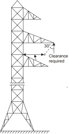
To meet the first point the ground wire as is said earlier is made of galvanized steel wire or ACSR wire and the protective angle decides the location of the ground wire for effective shielding. The second factor, i.e., adequate clearance between conductor and tower structure is obtained by designing a suitable length of the cross arm such that when a string is given a swing of 30° towards the tower structure the air gap between the power conductor and tower structure should be good enough to withstand the switching voltage expected on the system, normally four times the line-to-ground voltage (Fig. 3).
The clearances between the conductors also should be adjusted by adjusting the sag so that the mid-span flashovers are avoided. The third requirement is to have a low tower footing resistance economically feasible. The standard value of this resistance acceptable is approximately 10 ohms for 66 kV lines and increases with the operating voltage. For 400 kV it is approx. 80 ohms.
The tower footing resistance is the value of the footing resistance when measured at 50 Hz. The line performance with regard to lightning depends upon the impulse value of the resistance which is a function of the soil resistivity, critical breakdown gradient of the soil, length and type of driven grounds or counterpoises, and the magnitude of the surge current.
If the construction of the tower does not give a suitable value of the footing resistance, the following methods are adopted. One possibility could be the chemical treatment of the soil. This method is not practically possible because of the long length of the lines and because this method needs regular checks about the soil conditions. It is not possible to check the soil conditions at each and every tower of the line which runs over several miles. Therefore, this method is used more for improving the grounds of the substation.
The methods normally used for improving the grounds of transmission towers are the use of (i) ground rods, and (ii) counterpoises.
Ground Rods
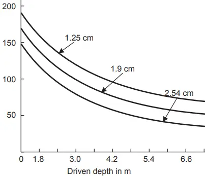
Ground rods are used to reduce the tower footing resistance. These are put into the ground surrounding the tower structure. Fig. 4 shows the variation of ground resistance with the length and thickness of the ground rods used. It is seen that the size (thickness) of the rod does not play a major role in reducing the ground resistance as does the length of the rod. Therefore, it is better to use thin but long rods or many small rods.
Counterpoise
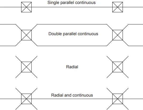
A counterpoise is a galvanized steel wire run in parallel or radial or a combination of the two, with respect to the overhead line. The various configurations used are shown in Fig. 5.
The corners of the squares indicate the location of the tower legs. The lightning stroke as is incident on the tower, discharges to the ground through the tower and then through the counterpoises. It is the surge impedance of the counterpoises which is important initially and once the surge has traveled over the counterpoise it is the leakage resistance of the counterpoise that is effective.
While selecting a suitable counterpoise it is necessary to see that the leakage resistance of the counterpoise should always be smaller than the surge impedance; otherwise, positive reflections of the surge will take place, and hence instead of lowering the potential of the tower (by the use of counterpoise) is will be raised.
The leakage resistance of the counterpoise depends upon the surface area, i.e., whether we have one long continuous counterpoise say 1000 m, or four smaller counterpoises of 250 m each, as far as the leakage resistance is concerned it is the same, whereas the surge impedance of say 1000 m if it is 200 ohms, then it will be 200/4 if there are four counterpoises of 250 m. each, as these four wires will now be connected in parallel.
Also if the surge takes say 6 micro-seconds to travel a distance of 1000 m to reduce the surge impedance to leakage impedance, with four of 250 m it will take 1.5. µ sec, that is, the surge will be discharged to the ground faster, the shorter the length of the ground wire.
It is, therefore, desirable to have many short counterpoises instead of one long counterpoise. But we should not have too many short counterpoises, otherwise, the surge impedance will become smaller than the leakage resistance (which is fixed for a counterpoise), and positive reflections will occur.
The question arises as to why we should have a low value of tower footing resistance. It is clear that, whenever lightning strikes a power line, a current is injected into the power system. The voltage to which the system will be raised depends upon what impedances the current encounters.
Say if the lightning stroke strikes a tower, the potential of the tower will depend upon the impedance of the tower. If it is high, the potential of the tower will also be high which will result in flashover of the insulator discs and result in a line-to-ground fault. The flashover will take place from the tower structure to the power conductor and, therefore, it is known as a back flashover.
Surge Absorbers
A surge absorber is a device that absorbs energy contained in a traveling wave.
Corona is a means of absorbing energy in the form of corona loss. A short length of cable between the equipment and the overhead line absorbs energy in the traveling wave because of its high capacitance and low inductance.
Another method of absorbing energy is the use of a Ferranti surge absorber which consists of an air core inductor connected in series with the line and surrounded by an earthed metallic sheet called a dissipator. The dissipator is insulated from the inductor by the air as shown in Fig. 6.
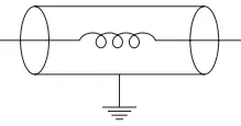
The surge absorber acts like an air-cored transformer whose primary is the low inductance inductor and the dissipator acts as the single-turn short circuit secondary.
Whenever the traveling wave is incident on the surge absorber a part of the energy contained in the wave is dissipated as heat due to transformer action and by eddy currents. Because of the series inductance, the steepness of the wave also is reduced. It is claimed that the stress in the end turns is reduced by 15% with the help of a surge absorber.
Related Posts
- Lightning Arrester Types & Working
- Lightning and Switching Voltage Protection Methods
- Personnel Protective Devices
- How Lightning Arrester Works
- Overvoltage Protection by Lightning Arresters
- Insulation coordination of Electrical Equipment
- MCCB Circuit Breakers
- Differential Protection of Generator & Alternator
- Types of Current Limiting Reactor
- Classification | Types of Protective Relays
- Fuse Selection Criteria
- Protection of Transmission lines by Ground Wires