Synchronous motors provide a precise, specific and constant speed for a wide range of loads, and are therefore used in preference to induction motors when constant speed operation is essential. Such machines are available over a very wide range from tiny single-phase versions in domestic timers to multi-megawatt machines in large industrial applications such as gas compressors.
Synchronous Motors
In the synchronous motor, the stator windings are exactly the same as in the induction motor, so when connected to the 3-phase supply, a rotating magnetic field is produced.
The synchronous motor has a rotor with either a d.c. excited winding (supplied via slip-rings), or permanent magnets, designed to cause the rotor to ‘lock-on’ or ‘synchronise with’ the rotating magnetic field produced by the stator.
Once the rotor is synchronised, it will run at exactly the same speed as the rotating field despite load variation, so under constant-frequency operation the speed will remain constant as long as the supply frequency is stable.
The synchronous speed (in rev/min) is given by the expression
Ns = 120f/p
Where f is the supply frequency and p is the pole number of the winding.
Hence for two-, four- and six-pole industrial motors the running speeds on a 50 Hz supply are 3000, 1500 and 1000 rev/min, while on a 60 Hz supply they become 3600, 1800 and 1200 rev/min, respectively.
Users who want speeds different from these will be disappointed, unless they are prepared to invest in a variable-frequency inverter.
With the synchronous machine we find that, there is a limit to the maximum (pull-out) torque which can be developed before the rotor is forced out of synchronism with the rotating field.
This ‘pull-out’ torque will typically be 1.5 times the continuous rated torque, but for all torques below pull-out the steady running speed will be absolutely constant.
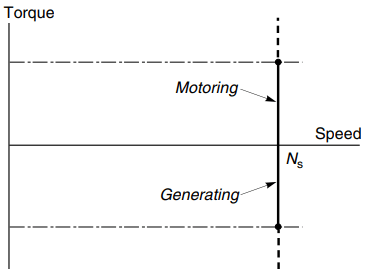
The torque–speed curve is therefore simply a vertical line at the synchronous speed, as shown in Figure 1. We can see that the vertical line extends into quadrant 2, which indicates that if we try to force the speed above the synchronous speed the machine will act as a generator.
The mains-fed synchronous motor is clearly ideal where a constant speed is essential, and also where several motors must run at precisely the same speed. They are also used where precise integral speed ratios are to be maintained: for example, a 3:1 speed ratio can be guaranteed by using a 2-pole and a 6-pole motor, fed from the same supply.
The excited-rotor type is given most weight not only because of its importance in large sizes but also because its behaviour can be analysed, and its mechanism of operation illuminated, by means of a relatively simple equivalent circuit.
Excited Rotor Synchronous Motors
The rotor carries a ‘field’ winding which is supplied with direct current via a pair of sliprings on the shaft, and is designed to produce an air-gap field of the same pole number and spatial distribution (usually sinusoidal) as that produced by the stator winding.
The rotor may be more or less cylindrical, with the field winding distributed in slots (see Figure 2(a)), or it may have projecting (‘salient’) poles around which the winding is concentrated (see Figure 2(b)).
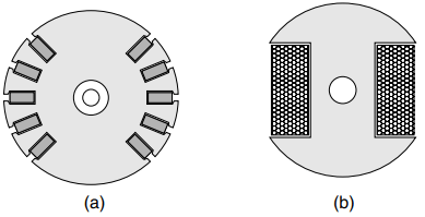
Excited-rotor motors are used in sizes ranging from a few kW up to several MW. The large ones are effective alternators (as used for power generation) but used as motors. Wound-rotor induction motors can also be made to operate synchronously by supplying the rotor with d.c. through the sliprings.
The simplest way to visualise the mechanism of torque production is to focus on a static picture, and consider the alignment force between the stator and rotor field patterns.
When the two are aligned with N facing S, the torque is zero and the system is in stable equilibrium, with any displacement to right or left causing a restoring torque to come into play.
If the fields are distributed sinusoidally in space, the restoring torque will reach a maximum when the poles are misaligned by half a pole pitch, or 90o. Beyond 90o the torque reduces with angle, giving an unstable region, zero torque being reached again when N is opposite to N.
When the motor is running synchronously, we can use much the same mental picture because the field produced by the 3-phase alternating currents in the stator windings rotates at precisely the same speed as the field produced by the d.c. current in the rotor.
At no-load there is little or no angular displacement between the field patterns, because the torque required to overcome friction is small.
But each time the load increases, the rotor slows momentarily before settling at the original speed but with a displacement between the two field patterns that is sufficient to furnish the torque needed for steady-state running.
This angle is known as the ‘load-angle’, and we can actually see it when we illuminate the shaft of the motor with a mains-frequency stroboscope: a reference mark on the shaft is seen to drop back by a few degrees each time the load is increased.
Equivalent Circuit of Excited Rotor Synchronous Motor
Predicting the current and power-factor drawn from the mains by a cylindrical-rotor synchronous motor is possible by means of the very simple per-phase a.c. equivalent circuit shown in Figure 3.
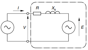
In this circuit Xs (known as the synchronous reactance) represents the effective inductive reactance of the stator phase winding; R is the stator winding resistance; V the applied voltage and E the e.m.f. induced in the stator winding by the rotating field produced by the d.c. current on the rotor.
Xs is effectively equal to the sum of the magnetising and leakage reactances, i.e. Xs = Xm + Xl: but because the air-gap in synchronous machines is usually larger than in induction motors, their per unit synchronous reactance is usually lower than that of an induction machine with the same stator winding.
The similarity between this circuit and that of the d.c. machine and the induction motor is clear, and it stems from the fact that these machines produce torque by the interaction of a magnetic field and current-carrying conductors (the so-called ‘BIl’ effect).
In the case of the d.c. machine the inductance was seen not to be important under steady-state conditions, because the current was steady (i.e. d.c.), and the resistance emerged as the dominant parameter.
In the case of the mains-fed synchronous motor the current is alternating at mains frequency, so not surprisingly we find that the synchronous reactance is the dominant impedance and resistance plays only a minor role.
Discussion of the equivalent circuit and the associated phasor diagram greatly assists the understanding of motor behaviour, especially its ability to operate over a range of power factors.
Our aim is to find the current drawn from the mains, which from Figure 3 clearly depends on all the parameters therein. But for a given machine operating from a constant-voltage, constant-frequency supply, the only variables are the load on the shaft and the d.c. current (the excitation) fed into the rotor, so we will look at the influence of both, beginning with the effect of the load on the shaft.
The speed is constant and therefore the mechanical output power (torque times speed) is proportional to the torque being produced, which in the steady state is equal and opposite to the load torque. Hence if we neglect the losses in the motor, the electrical input power is also determined by the load on the shaft. The input power per phase is given by VI cos ɸ, where I is the current and the power-factor angle is ɸ.
But V is fixed, so the in-phase (or real) component of input current (I cos ɸ) is determined by the mechanical load on the shaft.
The influence of the d.c. excitation current, at a given supply frequency (i.e. speed) the mains-frequency e.m.f., (E) induced in the stator is proportional to the d.c. field current fed into the rotor.
Phasor Diagram and Power Factor Control
To see how the magnitude of the e.m.f. influences behaviour we can examine the phasor diagrams of a synchronous machine operating as a motor, as shown in Figure 4.
The first point to clarify is that our sign convention is that motoring corresponds to positive input power to the machine. The power is given by VI cos ɸ, so when the machine is motoring (positive power) the angle ɸ lies in the range ±90o.
If the current lags or leads the voltage by more than 90o the machine will be generating. Figure 4 shows three phasor diagrams corresponding to low, medium and high values of the induced e.m.f., (E), the shaft load (i.e. mechanical power) being constant.
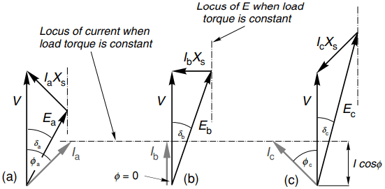
As discussed above, if the mechanical power is constant, so is I cosɸ, and the locus of the current is therefore shown by the horizontal dotted line.
The load angle (δ), is the angle between V and E in the phasor diagram. In Figure 4, the voltage phasor diagram embodies KirchhoV’s law as applied to the equivalent circuit in Figure 3, i.e.
V = E + IR + jIXs
But for the sake of simplicity R is neglected so the phasor diagram simply consists of the volt-drop IXs (which leads the current I by 90o) added to E to yield V.
Figure 4(a) represents a condition where the field current has been set so that the magnitude of the induced e.m.f., (E) is less than V. This is called an ‘under-excited’ condition, and as can be seen the current is lagging the terminal voltage and the power-factor is cos ɸa lagging.
When the field current is increased (increasing the magnitude of E) the magnitude of the input current reduces and it moves more into phase with V: the special case shown in Figure 4(b) shows that the motor can be operated at unity power-factor if the field current is suitably chosen.
Finally, in Figure 4(c), the field current is considerably higher (the ‘overexcited’ case) which causes the current to increase again but this time the current leads the voltage and the power-factor is cos ɸc leading.
We see that we can obtain any desired power-factor by appropriate choice of rotor excitation, and in particular we can operate with a leading power-factor.
This is a freedom not afforded to users of induction motors, and arises because in the synchronous machine there is an additional mechanism for providing excitation, as we will now see.
The stator winding of the synchronous motor is the same as the induction motor, so it is to be expected that the resultant flux will be determined by the magnitude and frequency of the applied voltage.
This flux will therefore remain constant regardless of the load, and there will be an associated requirement for magnetising MMF. But now we have two possible means of providing the excitation MMF, namely the d.c. current fed into the rotor and the lagging component of a.c. current in the stator.
When the rotor is underexcited, i.e. the induced e.m.f. E is less than V (Figure 4(a)), the stator current has a lagging component to make up for the shortfall in excitation needed to yield the resultant field that must be present as determined by the terminal voltage, V.
With more field current (Figure 4(b)), however, the rotor excitation alone is sufficient and no lagging current is drawn by the stator. And in the overexcited case (Figure 4(c)), there is so much rotor excitation that there is effectively some reactive power to spare and the leading power factor represents the export of lagging reactive power that could be used to provide excitation for induction motors elsewhere on the same system.
To conclude our look at the synchronous motor we can now quantify the qualitative picture of torque production by noting from the phasor diagrams that if the mechanical power (i.e. load torque) is constant, the variation of the load-angle (δ) with E is such that E sin δ remains constant.
As the rotor excitation is reduced, and E becomes smaller, the load angle increases until it eventually reaches its maximum of 90o, at which point the rotor will lose synchronism and stall.
This means that there will always be a lower limit to the excitation required for the machine to be able to transmit the specified torque. This is just what our simple mental picture of torque being developed between two magnetic fields, one of which becomes very weak, would lead us to expect.
Starting of Synchronous Motor
It should be clear from the discussion of how torque is produced that unless the rotor is running at the same speed as the rotating field, no steady torque can be produced.
If the rotor is running at a different speed, the two fields will be sliding past each other, giving rise to a pulsating torque with an average value of zero. Hence a basic synchronous machine is not self-starting, and some alternative method of producing a run-up torque is required.
Most synchronous motors are therefore equipped with some form of rotor cage, similar to that of an induction motor, in addition to the main field winding.
When the motor is switched onto the mains supply, it operates as an induction motor during the run-up phase, until the speed is just below synchronous.
The excitation is then switched on so that the rotor is able to make the final acceleration and ‘pull-in’ to synchronism with the rotating field. Because the cage is only required during starting, it can be short time rated, and therefore comparatively small. Once the rotor is synchronised, and the load is steady, no currents are induced in the cage, because the slip is zero.
The cage does, however, come into play when the load changes, when it provides an effective method for damping out the oscillations of the rotor as it settles at its new steady-state load angle.
Large motors will tend to draw a very heavy current during run-up, so some form of reduced voltage starter is often required.
Sometimes, a separate small induction motor is used simply to run-up the main motor before synchronisation, but this is only feasible where the load is not applied until after the main motor has been synchronised.
No special starter is required for the wound-rotor induction motor of course, which runs up in the usual way before the d.c. excitation is applied. Motors operated like this are sometimes known as ‘Inductosyns’.
Permanent Magnet Synchronous Motors
Permanent magnets are used on the rotor instead of a wound field: typical 2-pole and 4-pole surface-mounted versions are shown in Figure 5, the direction in which the magnets have been magnetised being represented by the arrows. Motors of this sort have outputs ranging from about 100 W up to perhaps 100 kW.
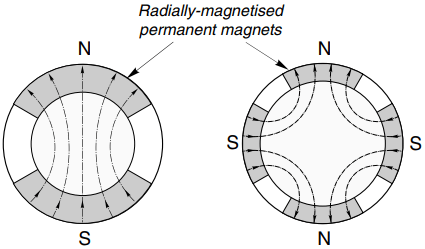
For starting from a fixed-frequency supply a rotor cage is required, as discussed above. The advantages of the permanent magnet type are that no supply is needed for the rotor and the rotor construction can be robust and reliable.
The disadvantage is that the excitation is fixed, so the designer must either choose the shape and disposition of the magnets to match the requirements of one specific load, or seek a general-purpose compromise. Control of power-factor via excitation is no longer possible.
Early permanent magnet motors suffered from the tendency for the magnets to be demagnetised by the high stator currents during starting, and from a restricted maximum allowable temperature.
Much improved versions using high coercivity rare-earth magnets were developed during the 1970s to overcome these problems. They are usually referred to as ‘Line-Start’ motors, to indicate that they are designed for direct-on-line starting.
The steady-state efficiency and power-factor at full load are in most cases better than the equivalent induction motor, and they can pull-in to synchronism with inertia loads of many times rotor inertia.