There are two categories of SCR, the fast turn-off inverter grade SCR and relatively slow turn-off converter grade SCR. Some of the properties of these are interdependent and designers have aimed to combine them in most suitable manner. The application therefore decides what category is to be chosen. Once the category is chosen in each category a choice of SCR is available depending upon:
- voltage rating
- current rating
- Type of package.
SCR Selection Criteria
Voltage Rating Selection of SCR
SCR are rated for maximum repetitive forward and reverse voltage ratings. SCR may be operated upto these ratings. Designers however choose a safety factor and a safety factor 2 to 2.5 is used for transient voltages. Generally, some form of overvoltage suppression is used but complete protection is not cost effective.
Excessive dv/dt causes misfiring of SCR. Such transients may be suppressed by CR snubber circuits across SCR. Snubber circuit cost and complexity must be considered in selecting proper dv/dt rating.
Current Rating Selection of SCR
Selection of current rating decides the size of the SCR. Current rating chosen may be the normal operating current level or maximum expected overload current. In data books SCR are categorized according to their current ratings. Unlike voltage rating, the current rating for a chosen SCR is rarely utilized.
Indirectly SCR current rating may be chosen by selecting the SCR by its junction to heatsink thermal impedance. SCR thermal impedance is given by:
SCR thermal impedance, Rth(j – h) = (T/P)oC/watt
where P = power dessipated in watts.
T = Temperature rise in oC.
Power dissipation in the SCR is caused by several factors such as conduction current and on-state voltage, leakage current under blocking voltage conditions, gate current and voltage, and switching losses.
SCR thermal impedance is an important characteristic. The larger the SCR smaller is its thermal impedance. Efficiency of the cooling system allows more power to be dissipated in a given SCR. In this case the cooling system cost may dictate use of larger SCR to reduce the cost of cooling system. However, efficient cooling system will reduce the size of the equipment.
Surge Current Rating Selection of SCR
In many applications a SCR may have withstand short circuit conditions due to short circuit until the circuit is interrupted by fuse or the circuit breaker. Surge current rating appropriate for the application has to be selected as the SCR may be subjected to such conditions several time in its lifetime.
dI/dt: A fast rise high gate pulse allows higher dI/dt. Inverter grade SCR usually have high dI/dt ratings however in the class available SCR may have various magnitudes of dl/dt. Choosing a SCR with high dI/dt rating reduces the cost of required inductance for limiting the value of dI/dt to which the SCR is subjected during its operation.
Package Selection of SCR
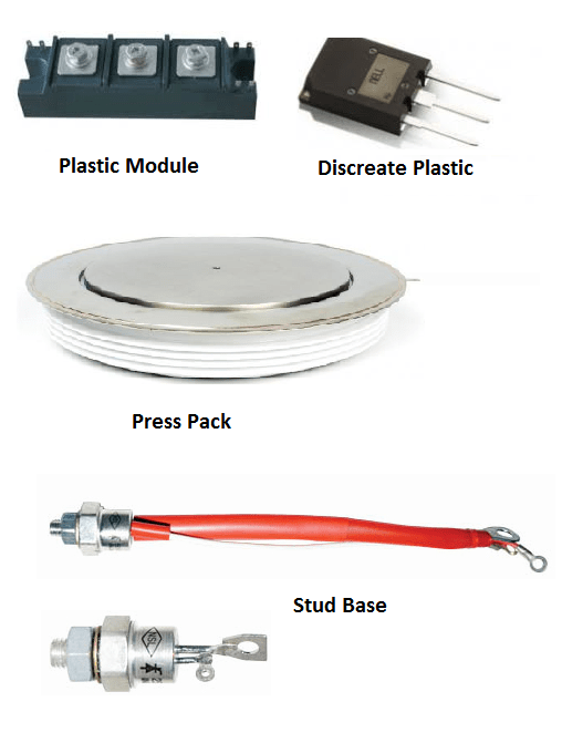
At present SCR are available five distinct packages such as
- Discrete plastic
- Plastic module
- Stud base
- Flat base and
- Press pack packages.
Discrete plastic package with planar type construction is the cheapest device available upto 25 A and 1000 V applications. Besides being cheap it is easily mounted in circuits with large number of other components.

Plastic modules have same advantages as in discrete plastic package except that it contains more than one device and is available in current ranges upto 100 A. These modules are attractive to user because they can be easily mounted into the circuit by bolting to the heatsink, without any insulation.
The stud base package is a good compromise between low thermal resistance and ease of mounting. This construction is used for current ranges between 5 to 150 A and full range of voltage. The disadvantage is that it is not easy to isolate this device from the heatsink.
Flat base devices have the same advantage as that of stud base plus advantage of isolating it from the heatsink by a thin layer of insulation. These devices are available from 10 to 400 A.
Press pack devices are used for very high currents exceeding 200 A and voltages exceeding 1200 V. The electrodes and SCR are contained in a ceramic envelope to provide the necessary isolation between anode and cathode. Clamping pressure is decided for safety of SCR assembly and minimum thermal and electrical contact resistance. As both the surfaces are clamped to heatsinks, minimum thermal resistance is achieved.
Thanks for reading about “scr selection criteria”.
Related Posts
- Operation of Thyristors
- Static Characteristics of SCR | Thyristor
- Silicon Controlled Rectifier Function
- Applications & Characteristics of SCR
- SCR Selection Criteria
- Thyristor | SCR Specifications and Ratings
- Operation of Triac & GTO
- Triac Working
- Characteristics, Operation, & Construction of IGBT
- Freewheeling Diode in Controlled Rectifier
- Reverse Recovery Characteristics of Power Diode