Ammeters and voltmeters affect the operation of circuits. The degree to which the circuits are affected is called the loading effect of the instrument. For an instrument to provide an accurate indication of how a circuit operates, the loading effect should ideally be zero.
In practice, it is impossible for any instrument to have zero loading effect, since all instruments absorb some energy from the circuit under test, thereby affecting circuit operation.
Voltmeter Loading Effect
When a voltmeter is placed across two terminals to provide a voltage reading, the circuit is affected in the same manner as if a resistance were placed across the two terminals.
If the resistance of the voltmeter is very large in comparison with the resistance across which the voltage is to be measured, the meter will indicate essentially the same voltage as that present before the meter was connected.
On the other hand, if the meter has an internal resistance which is near in value to the resistance across which the measurement is taken, then the meter will adversely load the circuit, resulting in an erroneous reading.
Generally, if the meter resistance is more than ten times larger than the resistance across which the voltage is taken, then the voltmeter loading effect is considered negligible and may be ignored.
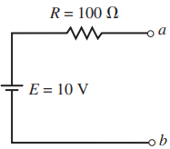
In the circuit of Figure 1, there is no current in the circuit since the terminals a and b are open circuited. The voltage appearing between the open terminals must be Vab 10 V.
Now, if we place a voltmeter having an internal resistance of 200 kΩ between the terminals, the circuit is closed, resulting in a small current. The complete circuit appears as shown in Figure 2. The reading indicated on the face of the meter is the voltage that occurs across the internal resistance of the meter.
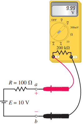
Applying Kirchhoff’s voltage law to the circuit, this voltage is

Clearly, the reading on the face of the meter is essentially equal to the expected value of 10 V. The loading effect of a meter as follows:

For the circuit of Figure 2, the voltmeter has a loading effect of

This loading error is virtually undetectable for the circuit given. The same would not be true if we had a circuit as shown in Figure 3 and used the same voltmeter to provide a reading. Again, if the circuit were left open circuited, we would expect that Vab 10 V.
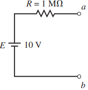
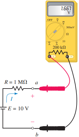
By connecting the 200-kΩ voltmeter between the terminals, as shown in Figure 4, we see that the voltage detected between terminals a and b will no longer be the desired voltage; rather,

The loading effect of the meter in this circuit is

The previous illustration is an example of a problem that can occur when taking measurements in electronic circuits. When an inexperienced technician or technologist obtains an unforeseen result, he or she assumes that something is wrong with either the circuit or the instrument.
In fact, both the circuit and the instrument are behaving in a perfectly predictable manner. The tech merely forgot to take into account the meter’s loading effect. All instruments have limitations, and we must always be aware of these limitations.
Example: Calculate the loading effects if a digital multimeter, having an internal resistance of 10 MΩ, is used to measure V1 and V2 in the circuit of Figure 5.
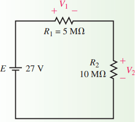
Solution: In order to determine the loading effect for a particular reading, we need to calculate both the unloaded voltage and the loaded voltage. For the circuit given in Figure 5, the unloaded voltage across each resistor is
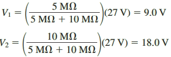
When the voltmeter is used to measure V1, the result is equivalent to connecting a 10-M resistor across resistor R1, as shown in Figure 6.
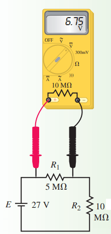
The voltage appearing across the parallel combination of R1 and resistance of the voltmeter is calculated as
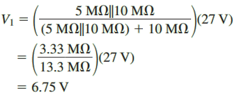
Notice that the measured voltage is significantly less than the 9 V that we had expected to measure.
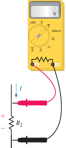
With the voltmeter connected across resistor R2, the circuit appears as shown in Figure 7. The voltage appearing across the parallel combination of R2 and resistance of the voltmeter is calculated as
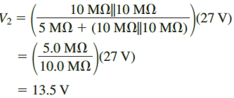
Again, we notice that the measured voltage is quite a bit less than the 18 V that we had expected.
Now the loading effects are calculated as follows:
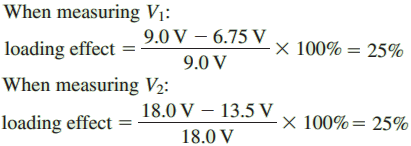
This example clearly illustrates a problem that novices often make when they are taking voltage measurements in high-resistance circuits.
If the measured voltages V1 = 6.75 V and V2 = 13.50 V are used to verify Kirchhoff’s voltage law, the novice would say that this represents a contradiction of the law (since 6.75 V + 13.50 V ≠ 27.0 V).
In fact, we see that the circuit is behaving exactly as predicted by circuit theory. The problem occurs when instrument limitations are not considered.
So, whenever an instrument is used to measure a quantity, the operator must always consider the loading effects of the instrument.