Temperature, the most frequently measured process variable on the planet, can be measured in various ways. Many temperature measurement devices incorporate a resistive material that when exposed to an environment, the resistance will change in response to the temperature in a predictable manner.
This style of sensor is referred to as a resistance temperature detector (RTD). The resistive materials used are nickel, copper, and most commonly platinum.
RTDs designed with platinum provide the most stable resistance versus temperature relationship and therefore can achieve accuracies capable for use as a primary reference standard.
The resistive material is “packaged” in a wide variety of approaches to achieve the performance required and to support the installation constraints of the measurement point in the process of concern.
There are many factors that should be considered in the design, selection, installation, integration, and monitoring of an RTD to ensure that the actual measurement meets the needs of the process.
This article discusses the principle of operation of an RTD, the general construction methods, common applications, how to select an RTD, interfacing an RTD with measurement instruments, and finally an overview of the types of errors that must be taken into consideration when using an RTD.
Resistance Temperature Detector Working
Common RTD sensing elements constructed of platinum copper or nickel have a unique, and repeatable and predictable resistance versus temperature relationship (R versus T) and operating temperature range.
The R versus T relationship is defined as the amount of resistance change of the sensor per degree of temperature change.
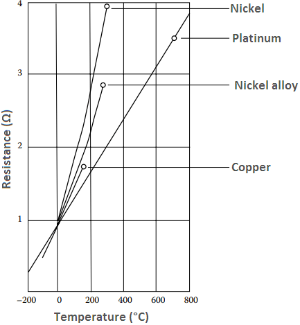
Figure 1 shows the resistance relationship for the most common metals used for RTDs and the temperature ranges.
R versus T Relationship of Various Metals
Platinum is a noble metal and has the most stable resistance to temperature relationship over the largest temperature range.
Nickel elements have a limited temperature range because the amount of change in resistance per degree of change in temperature becomes very nonlinear at temperatures over 572 °F (300 °C).
Copper has a very linear resistance to temperature relationship; however, copper oxidizes at moderate temperatures and cannot be used over 302 °F (150 °C).
Platinum is the best metal for RTDs because it follows a very linear resistance to temperature relationship and it follows the R versus T relationship in a highly repeatable manner over a wide temperature range.
The unique properties of platinum make it the material of choice for temperature standards over the range of −272.5 °C to 961.78 °C.
The basic differentiator between metals used as resistive elements is the linear approximation of the R versus T relationship between 0 °C and 100 °C and is referred to as alpha, α. Equation 1 defines α; its units are Ω/Ω/°C.

Where R0 is the resistance of the sensor at 0 °C R100 is the resistance of the sensor at 100 °C
Pure platinum has an alpha of 0.003925 Ω/Ω/°C and is used in the construction of laboratory-grade RTDs.
Conversely, two widely recognized standards for industrial RTDs IEC60751 and ASTM E-1137 specify an alpha of 0.00385 Ω/Ω/°C. Before these standards were widely adopted, several different alpha values were used.
It is still possible to find older probes that are made with platinum that have alpha values of 0.003916 Ω/Ω/°C and 0.003902 Ω/Ω/°C. These different alpha values for platinum are achieved by doping, basically carefully introducing impurities into the platinum. The impurities introduced during doping become embedded in the lattice structure of the platinum and result in a different R versus T curve and hence alpha value.
To characterize the R versus T relationship of any RTD over a temperature range that represents the planned range of use, calibration must be performed at temperatures other than 0 °C and 100 °C. Two common calibration methods are the fixed-point method and the comparison method.
Fixed-point calibration, used for the highest accuracy calibrations, uses the triple point, freezing point, or melting point of pure substances such as water, zinc, tin, and argon to generate a known and repeatable temperature. These cells allow the user to reproduce actual conditions of the ITS-90 temperature scale.
Fixed-point calibrations provide extremely accurate calibrations (within ±0.001 °C). A common fixed-point calibration method for industrial-grade probes is the ice bath. The equipment is inexpensive, easy to use, and can accommodate several sensors at once. The ice point is designated as a secondary standard because its accuracy is ±0.005 °C (±0.009 °F), compared to ±0.001 °C (±0.0018 °F) for primary fixed points.
In comparison calibrations, commonly used with secondary standard platinum resistance thermometers (SPRTs) and industrial RTDs, the thermometers being calibrated are compared to calibrated thermometers by means of a bath whose temperature is uniformly stable.
Unlike fixed-point calibrations, comparisons can be made at any temperature between −100 °C and 500 °C (−148 °F to 932 °F). This method might be more cost-effective since several sensors can be calibrated simultaneously with automated equipment.
These electrically heated and well-stirred baths use silicone oils and molten salts as the medium for the various calibration temperatures.
Resistance versus Temperature Relationship of PRT
After determining the platinum resistance thermometer’s (PRT) resistance at various temperature points, the R versus T curve can be defined. Once this has been done, any temperature can be determined from the measured resistance.
These equations are multivariable polynomials, and although complex, the various forms of the equations are typically incorporated into transmitters, handheld readouts, and temperature-related electronic devices to solve this challenge.
The two most common curve-fitting techniques are the ITS-90 and Callendar–Van Dusen equations. On January 1, 1990, the International Temperature Scale of 1990 (ITS-90) became the official international temperature scale.
Two reference functions are used to define the temperature coefficient for an ideal SPRT: one for temperatures below 0 °C and the other for temperatures above 0 °C.
When a PRT is calibrated on the ITS-90, the coefficients determined in the calibration are used to describe a deviation function that represents the difference between the resistance of the standard PRT and the reference function at all temperatures within the range.
Using the calibration coefficients and the deviation functions, the SPRT can be used to determine any temperature from its measured resistance. Because ITS-90 equations are complex, computer software is necessary for accurate calculations.
Not all PRT users need to follow the complex equations and computer programs associated with ITS-90. As a rule of thumb, if the minimum required uncertainty of measurement is less than 0.1 °C, one probably will want to use ITS-90. For uncertainty of measurements greater than 0.1 °C, the effect of the change in scales is relatively small.
Callendar–Van Dusen equations are interpolation equations that describe the temperature versus resistance relationship of industrial PRTs. These second- and fourth order equations can be programmed easily into many electronic controllers.
The equation for an RTD with a 100 Ω R0:
For the temperature range of 0 °C – 850 °C (32 °F – 1562 °F) is
R(t) = R0(1 + At + Bt2) (Equation 2)
For the temperature range −200 °C to 0 °C (−392 °F to 32 °F):
R(t) = R0[1 + At + Bt2 + C(t – 100)/t3] (Equation 3)
Where,
R(t) is the resistance of the PRT at temperature t
t is the temperature in °C
R0 is the nominal resistance of the PRT at 0 °C
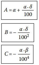
A, B, and C are constants based on calibration coefficients: α, δ, β (These coefficients and constants are generally provided by the calibration laboratory).
Expressions for the constants A, B, and C are
Expressions for the constants α, δ, and β are
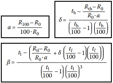
Where,
th is the high temperature in the calibration range (e.g., 260 °C).
tl is the low temperature in the calibration range (e.g., −196 °C).
Rth is the resistance of the sensor at the high temperature.
Rtl is the resistance of the sensor at the low temperature
Construction of Resistance Temperature Detector
There are many different types of RTDs for different applications. Generally, an RTD consists of three major components:
- Sensing element
- Protective housing
- Lead wires

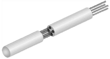
Figure 2 shows the construction of a typical industrial RTD; the tip is cut away to show the position of the sensing element. The selection of these three components is critical to the performance of the probe, and careful selection is required to ensure that the probe is suitable for the application.
(a). Sensing Element: All RTD elements are in essence a length of wire (whether coiled, wound, or deposited through vapor deposition as in the case of thin film) that becomes more resistive at higher temperature. But the resistance of these wires can also be affected by physical deformation or strain.
The two main causes of strain in RTDs come from thermal expansion of the wire relative to the electrically insulating support structure and from deformation of the wire due to shock or vibration.
All element designs attempt to minimize the effect of strain on the wire, but there is a trade-off between strain from thermal expansion versus shock and vibration.
This can be understood simplistically as the more firmly the wire is attached to the electrical insulator, the less likely it is able to move under shock and vibration conditions, but it is more likely to be stretched with the thermal expansion and contraction of the insulator.
There are three different categories of elements; each has their own particular characteristics:
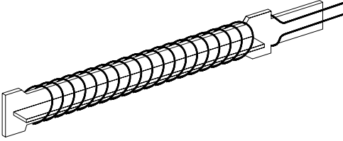
Strain Free Elements consist of platinum wire loosely coiled over a support structure so the element is free to expand and contract with temperature, but it is very susceptible to shock and vibration as the loops of platinum can sway back and forth causing deformation (see Figure 3).
Wire coil wound elements (or coil-in-the-hole elements) are coils of platinum placed in ceramic tubes that are filled with ceramic powder to support the coils, as in Figure 4. The powder supports the coil against some shock and vibration, and allows some movement for thermal expansion and contraction.
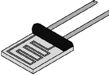
Thin Film elements are small squares of ceramic that have a thin film of platinum deposited on them, Figure 5. Some platinum is removed to form a zigzag patterned electrical path. The thin film of platinum does not move with shock and vibration but due to the small mismatch in coefficient of expansion between the platinum pattern and ceramic, thin films become less accurate over large temperature ranges. This limits their useful range.
A fourth type called externally wire wound is still used, but thin films and wire coil wound elements are generally preferred, and there are few instances where this older design is better than modern thin films or wire coil wound elements.
(b). Protective Housing: The protective housing has to ensure there is adequate thermal connection between the element and the measurement environment of interest, and at the same time protect the element from its soundings. Stainless steel probes are among the most common; a stainless steel tube closed at one end houses the element with the electrical connections coming out the other end. Many types of mounting fittings are available for various uses. Other types of probes use high-temperature plastics such as PTFE to encase the element.
The working temperature range of the probe is one of the criteria that will influence or limit the choices regarding the sheath material. For example, if stainless steel is used at elevated temperatures, the oxides formed can cause contamination of the platinum sensing element adversely affecting the accuracy of the probe.
How the element and lead wires are supported inside the protective housing is also critical. The materials used have to be capable of the temperature range, provide a good thermal path to the element, and isolate the element from the ambient vibrations without putting excessive strain on the element. Materials used include ceramic powder, heat sink compounds, and silicone RTVs.
(c). Lead Wires: When selecting the lead wire materials and the number of lead wires, consideration has to be given to the environment in which the probe will reside as well as the instrumentation to which it is going to interface. The element is basically a length of wire that changes in resistance with temperature.
In order to measure the resistance of the element, it must be wired to the measurement equipment in such a way that the resistance of the leads does not adversely affect the measurement. This is done in three ways, using two, three, or four wire connections.
Classification of Resistance Temperature Detectors
Though many types of element wire can be used to make RTDs, platinum has become the standard in both laboratory and industrial settings. Platinum RTDs are often called platinum resistance thermometers (PRTs).
RTDs utilizing other metals for the sensing element are only used in special applications or for measurements outside the PRT temperature range. The highest accuracy of all PRTs is the SPRTs. This accuracy is achieved at the expense of durability and cost.
The SPRT elements are wound from reference-grade platinum wire. Internal lead wires are usually made from platinum while internal supports are made from quartz or fuse silica. The sheaths are usually made from quartz or sometimes Inconel, depending on temperature range. Larger diameter platinum wire is used, which drives up the cost and results in a lower resistance for the probe (typically 25.5 Ω).
SPRTs have a wide temperature range (−200 °C to 1,000 °C) and approximately accurate to ±0.001 °C over the temperature range. SPRTs are only appropriate for laboratory use.
Another classification of laboratory PRTs is secondary SPRTs. They are constructed like the SPRT, but the materials are more cost-effective. SPRTs commonly use reference-grade, high–purity, smaller diameter platinum wire, metal sheaths, and ceramic-type insulators. Internal lead wires are usually a nickel-based alloy.
Secondary SPRTs are limited in temperature range (−200 °C to 500 °C) and are approximately accurate to ±0.03 °C over the temperature range.
Industrial-grade PRTs are designed to withstand industrial environments. They can be almost as durable as a thermocouple. Depending on the application, industrial PRTs can use thin film elements or coil wound elements.
The internal lead wires can range from PTFE insulated stranded nickel plated copper to silver wire, depending on the sensor size and application.
Sheath material is typically stainless steel; higher-temperature applications may demand Inconel. Other materials are used for specialized applications.
Applications of Resistance Temperature Detector
Sensor assemblies can be categorized into two groups by how they are installed or interface with the process:
- Immersion
- Surface mounted.
1. Immersion sensors take the form of an SS tube and some type of process connection fitting. They are installed into the process with sufficient immersion length to ensure good contact with the process medium and reduce external influences.
A variation of this style includes a separate thermowell that provides additional protection for the sensor. These styles are used to measure fluid or gas temperatures in pipes and tanks. Most sensors have the sensing element located at the tip of the stainless steel tube.
An averaging-style RTD, however, can measure an average temperature of air in a large duct. This style of immersion RTD has the sensing element distributed along the entire probe length and provides an average temperature. Lengths range from 3 to 60 ft.
2. Surface-mounted sensors are used when immersion into a process fluid is not possible due to configuration of the piping or tank, or the fluid properties may not allow an immersion-style sensor. Configurations range from tiny cylinders to large blocks that are mounted by clamps, adhesives, or bolted into place.
Most require the addition of insulation to isolate them from cooling or heating effects of the ambient conditions to ensure accuracy. Other applications may require special water proofing or pressure seals.
A heavy-duty underwater temperature sensor is designed for complete submersion under rivers, cooling ponds, or sewers. Steam autoclaves require a sensor that is sealed from intrusion by steam during the vacuum cycle process.
Immersion sensors generally have the best measurement accuracy because they are in direct contact with the process fluid. Surface-mounted sensors are measuring the pipe surface as a close approximation of the internal process fluid.
Selection Criteria of PRT
Selection of a PRT can be achieved by considering each of five criteria:
(1) Placement (2) Protection (3) Performance (4) Price (5) Service life
(1) Placement refers to how the sensor will be mounted in or on the process. Several factors influence which style is selected to achieve the desired measurement accuracy and longest service life.
An immersion style sensor usually provides the best accuracy but does require cutting a hole in the pipe or tank to allow for installation. A surface-mount sensor is the easiest to install and of lowest cost; however, some accuracy is sacrificed.
Placement considerations involve determining where in the piping or tank an entry can be made to accommodate an RTD and provide enough immersion length for an accurate measurement. The ideal immersion length to avoid external thermal influences is equal to 10 sensor or thermowell diameters plus the sensitive length (the element length).
For a direct immersion, 1/4 ft diameter RTD with a 1.0 in. element length, the minimum immersion would be 3.5 ft. A 1/4 ft diameter sensor with a thermowell should have at least 4.5 ft of immersion in the process.
For pipes less than 4 ft and other situations where sufficient immersion cannot be obtained, there are other solutions. Installing an elbow allows the RTD to be aligned parallel to the flow and extend down the pipe.
Other choices may be to use a surface mount RTD, or a modified immersion sensor that mounts flush to the inside of the process vessel.
(2) Protection refers to the items that are used to shield the sensor from the ambient conditions and from the process environment.
External to the process, a connection head is commonly used to provide a transition from the RTD leads to the facility wiring. In addition, it can provide protection from explosive atmospheres and keep water and other contaminants away from the sensor.
Any of these ambient conditions can, over time, cause sensor failure. To maintain protection from the process, a thermowell (Figure 6) can be used to protect the sensor from corrosive, erosive, high-velocity flow, high pressure, and vibration.
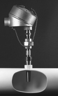
Another advantage of using a thermowell is that RTDs that need periodic calibration can be easily removed from the protective thermowell without draining the process.
(3) Performance includes factors such as probe accuracy, installation errors, long-term drift, and erosion or corrosion considerations. Accuracy of the sensor and accuracy of the measurement are most times quite different. Sensor accuracy is determined mostly by the manufacturing interchangeability and the style of sensing element.
The wire wound style has the widest temperature range and lowest drift, and a thin film element may have the same interchangeability but larger drift characteristics. Temperature range is often restricted by manufacturers to minimize the effect of drift on the sensor accuracy. Measurement accuracy includes the sensor accuracy and the installation affects. In addition, time response can be a large factor in the measurement accuracy. A sensor that does not keep pace with the process temperature change may be several degrees off from the actual temperature during thermal transients.
(4) Price, or from the user’s perspective, the cost is always a consideration. For any measurement point, the costs for maintenance, calibration, acquisition, and accuracy must be determined.
The initial cost of the RTD can be insignificant if a poor-quality inaccurate device is selected. A poor-quality RTD will waste energy, require frequent replacement, require more frequent calibration, and can reduce product quality.
A more expensive high-quality RTD will alleviate all of these problems and related expenses, resulting in the lowest life cycle cost for the measurement point.
(5) Service life of an RTD varies dramatically based on how and where the sensor is used. Two main factors that affect the life span are temperature cycling and vibration. All industrial-grade RTDs will drift over time and require periodic calibration to determine if they are still within tolerance. Vibration and wide temperature cycles can accelerate the drift rate possibly leading to premature failure.
Selecting the right RTD and following the selection criteria will ensure accuracy, long service life, and trouble-free temperature measurement.