As per present terminology, voltages less than 300 kV are termed as High Voltages. The voltages in the range of 300 kV to 765 kV are known as Extra High Voltages (EHV). The voltages which are 765 kV are termed as Ultra High Voltage (UHV). In India, transmission voltage ranges from 66 kV to 400 kV (RMS value of line-to-line voltage in the three-phase system). There are several advantages of extra high voltage transmission.
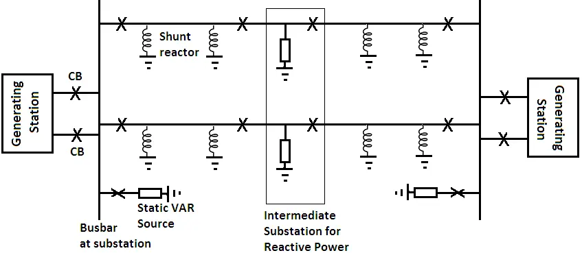
In EHV AC lines additional parallel three-phase line is always provided to ensure continuity of power supply and stability of line. A long EHV AC line is always a double circuit line with intermediate substations at an interval of 250 km to 400 km for compensating reactive power.
Electrical energy is generated at a voltage of about 11 kV. Then it is stepped up to 132, 220, or 400 kV for transmission. Electrical power transmission is preferred at high voltages because it has many advantages. The advantages of extra high voltage transmission will be obvious from the following discussion.
Power transmitted is given by P = √3 V I cos φ; where, V = transmission voltage, I = load current, cos φ = load power factor.
Or Load current, I = P/( √3 V cos φ)
From the above expression, it is clear that for a constant power and power factor, the load current is inversely proportional to the transmission voltage. In simple words, as we increase the transmission voltage, the load current decreases. This decrease in load current results in the following advantages:
Advantages of EHV AC Transmission
- As the current gets reduced, the size and volume of the conductor required also reduces for transmitting the same amount of power.
- Voltage drop in line (3IR) reduces and hence voltage regulation of the line is improved.
- Line losses (3I2R) get reduced which increases transmission line efficiency.
Some other advantages of extra high voltage transmission are as under:
- The power handling capacity of the line increases as we increase the transmission voltage. It is proportional to the square of the operating voltage. The costs related to towers, insulators, and different types of equipment are proportional to voltage rather than the square of voltage. Thus the net capital cost of the transmission line decreases as voltage increases. Therefore, a large power can be transmitted with high-voltage transmission lines economically.
- The total line cost per MW per km decreases considerably.
- The operation of the EHV AC system is simple, reliable, and can be adopted easily.
- The lines can be easily tapped and extended.
Disadvantages of EHV AC Transmission
The major problems in this system are as under.
- Corona loss is a big problem at higher voltages. This may further increase in bad weather conditions.
- It increases radio interference.
- The height of towers and insulation increases with an increase in transmission voltage.
- The cost of different types of equipment and switchgear required for transmission increases with an increase in transmission voltage.
- The high-voltage lines produce electrostatic effects which are injurious to human beings and animals.
Configuration of EHV AC Transmission
The typical configuration of a very long EHV / UHV three-phase AC transmission system is shown in Fig.

EHV AC transmission line requires a minimum two parallel three-phase transmission circuits to ensure reliability and stability during a fault on any one phase of the three-phase lines.
Similarly, the EHV line also requires one or more intermediate substations for installing series capacitors, shunt reactors, switching, and protection equipment. Generally, an intermediate substation is required at an interval of 250 to 300 km.
Line Compensation
With the increase in load demand, it becomes necessary to make use of high-voltage transmission lines for transmitting power over long distances. With improved design and other technical considerations, the high-voltage lines can be used for transmitting power for the maximum possible length of the line. But this may turn out to be expensive in certain cases. In such cases, the alternative is to increase the transmission capability of EHV transmission systems.
The capacity of these power transmission lines can be increased by using conventional methods such as choosing higher transmission voltages, higher speed breakers, intermediate switching stations, and reduced reactances of generators and transformers.
The transient stability limit can be increased using high-speed excitation systems. The series impedance of the line can be reduced by the use of bundled conductors which increases the stability limits.
The modern technique of artificially reducing the series reactance and shunt susceptance of the lines by using series capacitors and shunt susceptance of the lines by using series capacitors and shunt reactors is called compensation. With this compensation, the system stability is improved. Similarly, the power transmission efficiency is increased along with voltage control. It also helps in reducing transient overvoltages.
If series capacitors are used the line reactance is compensated directly and losses are reduced. The voltage conditions will be improved instantaneously with wide fluctuating loads. Power transfer ability is improved along with power factor.
With shunt capacitors, the phase angle between the voltage and the current is reduced which has various advantages.
When total reactive power obtained from series and shunt compensation is known then the maximum power transfer capability, voltage control conditions and efficiency of the line depend on the number, location, and circuit arrangements of the series capacitor and the shunt reactor.
For a long transmission line, it is required to find the most appropriate location for capacitors and reactors in addition to the compensation required for a particular line. The optimum possible solution must be obtained.
Thus in summary we can say that to get a better voltage profile, correction of power factor, and load balancing, compensation is required.
Series Compensation
This is one of the methods of reactive power control. The compensation of a transmission line with the help of a series capacitor is called series compensation. For compensating the series reactance of the line the series capacitor is inserted in the line at a specified point. This type of compensation is provided for long transmission lines having voltages of 220 kV and above.
A series capacitor in an a.c. circuit introduces negative or leading reactance. Current through this negative reactance causes a voltage drop that leads the current by 90°. This drop is opposite to that across an inductive reactance. Thus a series capacitor at rated frequency compensates for the drop or part of the drop through the inductive reactance of the feeder.
The conditions XL <XC, XL = XC, XL >XC are referred to as over-compensation, full-compensation, and under-compensation respectively. Over-compensation is not used in transmission systems. However, application of this type is sometimes found in distribution systems.
Advantages of Series Compensation
- Increase in power transmission capacity of the line.
- Improvements in system stability: The system stability margin is improved with the installation of series capacitors. The practical study shows that among the various methods of stability improvement of the system, the series capacitor is the most economical solution.
- Improved voltage regulation: The series capacitor reduces the line reactance and also improves the voltage on the load side which helps in improving the regulation of the transmission line.
- Load division between parallel circuits: Whenever a transmission system is to be strengthened by the addition of a new line or when one of the existing circuits is to be adjusted for parallel operation to achieve maximum power transfer, series compensation proves to be effective and helpful. The series capacitors help to equalize or adjust the power-sharing between the lines.
- Damping effect:The series capacitor helps to damp out the power swings and transient affected oscillations.
Disadvantages of Series Compensation
- The series capacitor adversely affects the short circuit rating of the circuit breaker and/or fuses in case the system encounters a fault as the series capacitor reduces the reactance of the line and increases the fault current level.
- A series capacitor changes the natural resonant frequency of the transmission system. In case of disturbances if the frequency of disturbance is equal to sub-synchronous frequency a phenomenon called subsynchronous resonance occurs. If the frequency is close to the resonant frequency of the generator shaft then it gives rise to its high torsional stresses.
- When a series capacitor is installed in the EHV line between a transformer and a source of supply a phenomenon known as ferroresonance may occur. Under this condition, a high voltage may appear across the capacitor terminals which may damage the capacitor itself. Similarly, it may cause severe over-voltage problems in the associated network.
- The series capacitor may cause faulty operation of distance relays of the line protection if the degree of compensation and location of the capacitor are not proper.
- Because of the series capacitor, the inductive reactance reduces so the possibility of hunting increases.
- When a fault occurs on a line carrying the series capacitors then the fault current flows through the series capacitors which increases the voltage across the capacitor to a high value which may damage the series capacitor and break the continuity of the supply. Hence the protection circuitry should be installed.
- If the series capacitor is taken out of the line due to internal faults or external faults then to maintain the continuity of supply, the circuit breakers, isolators, and control circuitry which is quite costly are required. So overall cost of the series capacitor increases.
Circuit Arrangements with Series Capacitor
In a transmission line, the series capacitors can be connected in various ways. The series capacitors can be located in line sections and switched on as part of the line. The various factors on which transmission line capability depends are as follows:
- Thermal limits of conductor: When heating due to current flow exceeds the allowable limit then we say the limit of conductors is reached. It is experienced on short circuits.
- Transient and steady-state stability: Transient stability is the limit on long lines while steady state stability is the limit on short lines. With series compensation, the series reactance of the line reduces. Thus the steady state stability criterion may limit the capability of compensated lines.
- Transmission line capability depends on overvoltage at the capacitor terminals of the series compensated line.
Shunt Compensation
The provision of a shunt compensation involves the insertion of a shunt capacitor across the line to improve the power factor and voltage as well as to reduce losses.
Unlike the effect with a series capacitor, the voltage rise is distributed uniformly along the length of the line.
The phase angle between the voltage and the current is reduced when a shunt capacitor is applied. It has the following effects.
- It reduces line current losses owing to the generation of reactive power.
- It reduces the transmission line current to a value less than the current in the load.
- It improves the power factor of the transmitted power.
- It reduces the voltage drop uniformly along the length of the line.
Advantages
As the power factor is improved with a shunt capacitor, we get the following advantages:-
- The kW of alternators, transformers, and lines are increased.
- The line current is reduced.
- The losses in power transformers and cables are reduced which saves energy.
- It prevents the overloading of transformers and switchgear.
- Improved voltage is obtained at the receiving end.
- The life of connected equipment like cables, switchgear, etc. is increased due to improved voltage and reduced current.
- It saves penalty imposed by electricity boards for lower power factor.
Disadvantage
The only disadvantage with a shunt capacitor is that the response to voltage dips is not as rapid as with a series capacitor since the switching of the bank is initiated by a change in voltage.
In some cases, the shunt compensation is done with the help of shunt reactors, especially for long transmission lines. When the long transmission lines are running under no load or light load conditions then it is required that the charging current should be less than the rated full load current of the line.
This can be achieved by connecting several inductors between the line and neutral at appropriate places along the line.The other advantage of connecting the shunt reactor is that the receiving end voltage is kept within the permissible limits which would otherwise be high due to the Ferrenti effect. The shunt reactors absorb some of the leading VARS for achieving voltage control.
Capacitors are connected either directly to a bus or through the tertiary winding of the main transformer.
Comparison between Series and Shunt Capacitors
- The rise in voltage due to a shunt capacitor is uniformly distributed along the length of the transmission line whereas in the case of series capacitors the rise in voltage is sudden where the capacitor is installed.
- For the same rise in voltage the reactive power capacity of a a shunt capacitor is greater than that of a series capacitor.
- The power factor is improved because of a shunt capacitor while the p.f. is little affected by a series capacitor.
- The series capacitors are found to be more effective for improving the system stability in case of long transmission lines.
Why Bundled Conductors are Used for EHV AC Transmission
The size of conductors is usually selected based on continuous and short-time current handling capacity for the transmission lines up to 220 kV. But for EHV AC lines, the effect of corona and radio interference is also to be taken into consideration while deciding conductor size. The selected conductor must give satisfactory performance for corona and radio interference. The conductor used in EHV AC lines is normally larger in size as only its current carrying capacity is not considered.
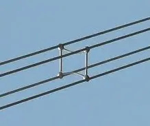
The bundled conductors are used for EHV AC lines. These conductors in effect control the voltage gradiant at the surface of the conductor due to which corona loss and radio interference are reduced.
With the use of only one conductor per phase and the size of the conductor determined by considering current handling capacity in the case of EHV lines, the voltage gradiant at the surface of the conductor is between 20 – 30 kV peak per cm which is beyond the accepted range.
One of the alternatives to this is the use of expanded conductors having filler material or airspaces in the inner side. This increases the outer radius reducing corona loss. But the expanded conductors should be handled very carefully to avoid distortion due to which voltage gradiant is increased. Also, these conductors face difficulties in manufacturing. Thus these conductors are rarely used in practice.

The other solution is to use two or more subconductors per phase so that lower maximum and average voltage gradiant than the single conductor with the same conductivity can be obtained. By using more conductors per phase, the voltage gradiant near the line is lowered which helps in reducing the possibility of corona discharge. It also helps in minimizing the interference with communication circuits. This reduces the circuit inductance which subsequently increases the stability margin and decreases voltage drop. So circuit capacity is increased and operating voltage is boosted up.
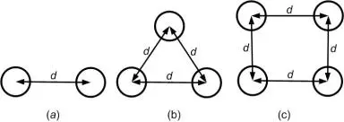
The number of conductors per phase may be 2, 3, 4, or 8. The three-conductor bundle consists of conductors placed at vertices of an equilateral triangle while the bundle of four conductors has the conductors placed at corners of a square. The spacing between the conductors is around 40 cm. These arrangements are shown in Fig.

The spacers are required to be placed at intervals of around 80 to 100 m in each span when bundled conductors are used. With the help of spacers, the spacing between the subconductors is maintained. This avoids the possibility of stucking up of subconductors because of wind forces or electromagnetic induction caused due to heavy currents.
The electromagnetic forces are proportional to the square of current while inversely proportional to the spacing between conductors. Thus the load current is sufficient to hold the conductors in contact once they come near to each other.
The increase in spacing between the subconductors does not increase the surge impedance loading to an appreciable extent. So the spacing within the bundle is not critical. The most commonly used spacing within the subconductors is 45 cm. The towers employing bundled conductors are required to be stronger as these conductors are subjected more to ice and wind loading than the single conductor of the same cross-section.