4 – 20 mA Signal Transmission
There are a wide variety of sensors available to provide us with electrical signals representing many different parameters which we wish to measure. All these devices have different characteristics of signal type, amplitude and linearity.
To make use of them in an industrial environment it is useful to convert their signals into a standard signal which we can connect to our measuring and control equipment. We are then able to use the same measuring and control equipment to process many different physical parameters. The most popular standards worldwide are given below:
- 0 – 5V
- 0 – 10V
- 1 – 5V
- 2 – 10V
- 1 – 5mA
- 0 – 20mA
- 4 – 20mA
- 10 – 50mA
We will discuss the 4 – 20 mA signal transmission in detail.
4 – 20 mA Signal Transmission
The transmitter is a current sinking circuit, which means that it will attempt to draw a current from an external power supply. This is usually a 4 – 20 mA signal powered from 24V DC which is often an integral part of the measuring instrument to which the transmitter is connected.
Unlike voltage transducers which are wired in parallel to measuring instruments, the current transmitter is wired in a series circuit. Multiple series loads, wide variation in supply voltage, and some inherent noise immunity are advantages of current loop transmitters.
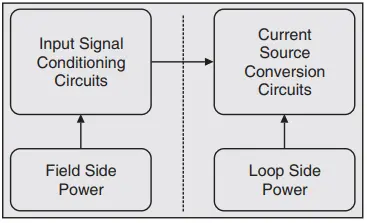
Fig. 1 shows the basic internal circuit blocks of a 4-20 mA transmitter. These circuits provide the following functionality;
Input Signal conditioning circuits provide appropriate interfacing for all types of inputs, such as; thermocouples, RTDs, AC-DC voltages and currents, strain gauges. Many 4-20 mA modules have “smart” signal conditioning functionality that provides linearization, and mathematical manipulations.
Power circuits generate all the necessary internal voltages required and are energized from either a local power source or the actual current loop. Current conversion circuits establish the 4-20 mA current loop signal.
The dashed line in illustrates isolation between the field side and the output loop side. Isolation is an extremely important aspect of signal transmission. Signal loops, power supplies, and grounds should always be completely isolated from each other.
There are basic three types of transmitter. They are discussed below:
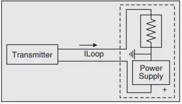
1. 2-Wire Transmitter: Fig. 2 shows a 2-wire transmitter energized by the loop current where the loop source voltage (compliance) is included in the receiver. The transmitter floats and signals ground is in the receiver.
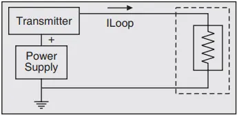
2. 3-Wire Transmitter: Fig. 3 shows 3-wire transmitter energized by a supply voltage at the transmitter. The transmitter sources the loop current. Transmitter common is connected to receiver common.
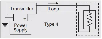
3. 4-Wire Transmitter: Fig. 4 shows a 4-wire transmitter energized by a supply voltage at the transmitter. The transmitter sources the loop current to a floating receiver load.
If a transmitter has field inputs, which provide signals referenced to field grounds potential ground loops exist. This potentially will cause signal gradation. In practical the field inputs are usually referenced to field grounds or in some cases actually connected to a field ground for example, the grounded thermocouple. Receiver grounds are rarely identical to field grounds, therefore, isolation is required to eliminate potential ground loop problems.
4 – 20 mA Current Loop
The 4 – 20 mA current loop is a very robust sensor signaling standard. Current loops are ideal for data transmission because of their inherent insensitivity to electrical noise.
In a 4 – 20 mA current loop, all the signaling current flows through all components, the same current flows even if the wire terminations are less than perfect. All the components in the loop drop voltage due to the signaling current flowing through them.
The signaling current is not affected by these voltage drops as long as the power supply voltage is greater than the sum of the voltage drops around the loop at the maximum signaling current of 20 mA.
In a 4 – 20 mA signal we always have at least 4 mA flowing in the loop. This means that if we can power our electronics from the 4 mA we can have our power supply and signal on the same pair of conductors.
An instrument which transmits a 4 – 20 mA signal is usually referred to as a transmitter and if it derives its power from the 4 mA residual current it is called a loop powered transmitter. The two “Rwire” symbols represent the resistance of the wires running out to the sensors and back to the power supply and controller.
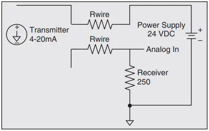
Fig. 5 shows a circuit of the simplest 4 – 20 mA current loop. The current supplied from the power supply flows through the wire to the transmitter and the transmitter regulates the current flow within the loop. The current allowed by the transmitter is called the loop current and it is proportional to the parameter that is being measured.
The loop current flows back to the controller through the wire, and then flows through the Rreceiver resistor to ground and returns to the power supply. The current flowing through Rreceiver produces a voltage that is easily measured by an analog input of a controller. There are four components:
1. The Power Supply. Power supplies for 2-wire transmitters must always be DC because the change in current flow represents the parameter that is being measured. If AC power were used, the current in the loop would be changing all the time.
Therefore, the change in current flow from the transmitter would be impossible to distinguish from change in current flow caused by the AC power supply. For 4-20 mA loops with 2-wire transmitters, common power supply voltages are 36 VDC, 24 VDC, 15 VDC and 12 VDC.
2. The Transmitter. The transmitter is the heart of the 4 – 20 mA signaling system. Here we use 2-wire transmitter. It converts a physical property such as temperature, humidity or pressure into an electrical signal. This electrical signal is a current, proportional to the temperature, humidity or pressure being measured.
In a 4 – 20 mA loop, 4 mA represents the low end of the measurement range and 20 mA represents the high end. The lower voltage is the minimum voltage necessary to guarantee proper transmitter operation. The higher voltage is the maximum voltage the transmitter can withstand and operate to its stated specifications.
3. The Receiver Resistor. A receiver resistor that converts the current signal to a voltage. It is much easier to measure a voltage than it is to measure a current. Therefore, many current loop circuits use a Receiver Resistor (Rreceiver) to convert the current into a voltage.
4. The Wire. It sending current through a wire produces a voltage drop proportional to the length and thickness of the wire. All wire has resistance, usually expressed in Ohms per 1,000 feet. The voltage drop is calculated by using Ohm’s law.