Magnetic Flowmeters
When an electrical conductor moves perpendicular to a magnetic field, a voltage is induced in that conductor perpendicular to both the magnetic flux lines and the direction of motion.
This phenomenon is known as electromagnetic induction, and it is the basic principle upon which all electro-mechanical generators operate.
In a generator mechanism, the conductor in question is typically a coil (or set of coils) made of copper wire. However, there is no reason the conductor must be made of copper wire.
Any electrically conductive substance in motion is sufficient to electromagnetically induce a voltage, even if that substance is a liquid. Therefore, electromagnetic induction is a technique applicable to the measurement of liquid flow rates.
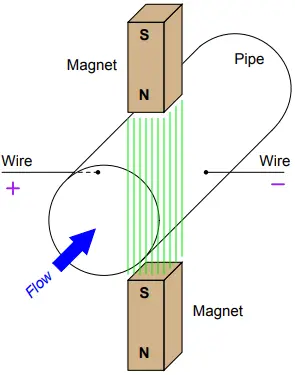
We can calculate flow rates with the help of following formula:
Q = kπdε ÷ 4B
Where, Q = Volumetric flow rate (cubic meters per second), ε = Motional EMF (volts), B = Magnetic flux density (Tesla), d = Diameter of flowtube (meters), k = Constant of proportionality.
Note the linearity of this equation. Nowhere do we encounter a power, root, or other nonlinear mathematical function in the equation for a magnetic flowmeter. This means no special characterization is required to calculate volumetric flow rate.
A few conditions must be met for this formula to successfully infer volumetric flow rate from induced voltage:
- The liquid must be a reasonably good conductor of electricity (note: it is okay if the conducting fluid contains some non-conducting solids; the conductive fluid surrounding the non-conducting solid matter still provides electrical continuity between the electrodes necessary for induction)
- The pipe must be completely filled with liquid to ensure contact with both probes as well as to ensure flow across the entire cross-section of the pipe
- The flowtube must be properly grounded to avoid errors caused by stray electric currents in the liquid
The first condition is met by careful consideration of the process liquid prior to installation. Magnetic flowmeter manufacturers will specify the minimum conductivity value of the liquid to be measured. The second and third conditions are met by correct installation of the magnetic flowtube in the pipe. The installation must be done in such a way as to guarantee full flooding of the flowtube (no gas pockets).
The flowtube is usually installed with electrodes across from each other horizontally (never vertically!) so even a momentary gas bubble will not break electrical contact between an electrode tip and the liquid flowstream. The following photograph shows how not to install magnetic flowmeters:
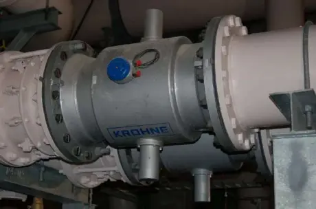
Note in this example how the electrodes are vertically oriented instead of horizontal, because the pipes for these two magnetic flowmeters were placed too close to allow proper clearance for the protruding electrodes to lie horizontally.
Sadly, poor flowmeter installation is all too common in new projects, as many piping designers and pipefitters are ignorant of flowmeter operating principles. This is one way instrument engineers and technicians may deter operational problems: by involving themselves in the design phase of a piping system, and helping to educate piping designers.
Magnetic flowmeters exhibit several advantages over other types of flowmeter. They are fairly tolerant of swirl and other large-scale turbulent fluid behavior, because the induced voltage is proportional only to the perpendicular velocity of the conductor, in this case the velocity of the fluid along the centerline of the flowtube.
As such, magnetic flowmeters do not require the long straight-runs of pipe upstream and downstream that orifice plates do, which is a great advantage in many piping systems. Upstream straight-pipe requirements of 5 diameters and downstream straightpipe requirements of 3 diameters is typical.
Additionally, the wide-open bore of a magnetic flowmeter’s tube means there is absolutely nothing to restrict the flow, resulting in extremely low permanent pressure loss.
The lack of any obstruction within the path of fluid flow means magnetic flowmeters are quite tolerant of solids within the liquid flowstream, making them well-suited for measuring such process liquids as wastewater, slurries, wood pulp, and food products which might clog other types of flowmeters.
In fact, magnetic flowmeters are the dominant flowmeter technology used in wastewater, wood pulping, and food processing industries for this very reason.
Electrical conductivity of the process liquid must meet a certain minimum value, but that is all. It is surprising to some technicians that changes in liquid conductivity have little to no effect on flow measurement accuracy. It is not as though a doubling of liquid conductivity will result in a doubling of induced voltage!
Motional EMF is strictly a function of physical dimensions, magnetic field strength, and fluid velocity. Liquids with poor conductivity present a greater electrical resistance in the voltage-measuring circuit than liquids with good conductivity, but this is of little consequence because the input impedance of the detection circuitry is phenomenally high.
The effect of liquid conductivity on flowmeter operation may be modeled by the following DC circuits:
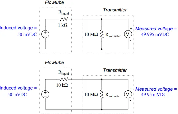
Here, a ten-fold (one order of magnitude) change in liquid resistance barely affects the measured voltage (49.995 mV versus 49.95 mV) because the flow transmitter’s voltage-sensing electronic circuit has such a high input impedance.
The liquid’s equivalent resistance value must increase dramatically beyond the values shown in this example before it will have any significant effect on flow measurement accuracy.
In fact, the only time fluid conductivity is a problem with magnetic flowmeters is when the fluid in question has negligible conductivity.
Such fluids include deionized water (e.g. steam boiler feedwater, ultrapure water for pharmaceutical and semiconductor manufacturing) and oils. Most aqueous (water-based) fluids work fine with magnetic flowmeters.
Proper grounding of the flowtube is very important for magnetic flowmeters. The motional EMF generated by most liquid flowstreams is very weak (1 millivolt or less!), and therefore may be easily overshadowed by noise voltage present as a result of stray electric currents in the piping and/or liquid.
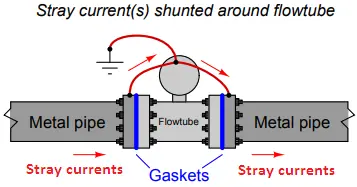
To combat this problem, magnetic flowmeters are usually equipped with grounding conductors placed to shunt (bypass) stray electric currents around the flowtube so the only voltage intercepted by the electrodes will be the motional EMF produced by liquid flow, and not voltage drops created by stray currents through the resistance of the liquid.
The following photograph shows a Rosemount model 8700 magnetic flowtube, with two braided46-wire grounding straps clearly visible:
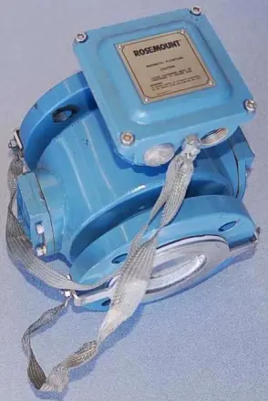
Note how both grounding straps attach to a common junction point on the flowtube housing. This common junction point should also be bonded to a functional earth ground when the flowtube is installed in the process line.
On this particular flowtube you can see a stainless steel grounding ring on the face of the near flange, connected to one of the braided grounding straps.
An identical grounding ring lays on the other flange, but it is not clearly visible in this photograph. These rings provide points of electrical contact with the liquid in installations where the pipe is made of plastic, or where the pipe is metal but lined with a plastic material for corrosion resistance.
If the pipe connecting to a magnetic flowmeter’s flowtube is conductive (e.g. metal), grounding may be accomplished by joining the metal pipes’ flanges together with grounding straps to a common grounding point on the flowtube body as such:
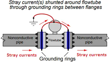
If the pipe connecting to a magnetic flowmeter’s flowtube is non-conductive (e.g. plastic) or conductive with an insulating lining (e.g. metal pipe with plastic lining), grounding to the pipe flanges will be pointless. In order for flowtube grounding to be effective, the grounding conductors must have electrical continuity to the fluid itself.
Special grounding rings may be sandwiched between the flanges of non-conducting pipes to provide points of electrical contact with the fluid. These grounding rings are then joined together with grounding straps to a common grounding point on the flowtube body as such:
Some magnetic flowmeters have their signal conditioning electronics located integral to the flowtube assembly.
Other magnetic flowmeters have separate electronics and flowtube assemblies, connected together by shielded cable. In these installations, the electronics assembly is referred to as the flow transmitter (FT) and the flowtube as the flow element (FE).
While in theory a permanent magnet should be able to provide the necessary magnetic flux for a magnetic flowmeter to function, this is never done in industrial practice. The reason for this has to do with a phenomenon called polarization which occurs when a DC voltage is impressed across a liquid containing ions (electrically charged molecules). Electrically-charged molecules (ions) tend to collect near poles of opposite charge, which in this case would be the flowmeter electrodes.
This “polarization” would soon interfere with detection of the motional EMF if a magnetic flowmeter were to use a constant magnetic flux such as that produced by a permanent magnet.
A simple solution to this problem is to alternate the polarity of the magnetic field, so the motional EMF polarity also alternates and never gives the fluid ions enough time to polarize.
This is why magnetic flowmeter tubes always employ electromagnet coils to generate the magnetic flux instead of permanent magnets. The electronics package of the flowmeter energizes these coils with currents of alternating polarity, so as to alternate the polarity of the induced voltage across the moving fluid.
Permanent magnets, with their unchanging magnetic polarities, would only be able to create an induced voltage with constant polarity, leading to ionic polarization and subsequent flow measurement errors.
A photograph of a Foxboro magnetic flowtube with one of the protective covers removed shows these wire coils clearly (in blue):
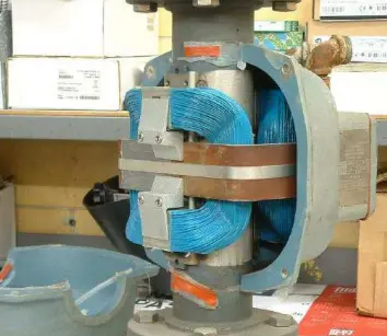
Perhaps the simplest form of coil excitation is when the coil is energized by 60 Hz AC power taken from the line power source, such as the case with this Foxboro flowtube.
Since motional EMF is proportional to fluid velocity and to the flux density of the magnetic field, the induced voltage for such a coil will also be a 60 Hz sine wave whose amplitude varies with volumetric flow rate.
Unfortunately, if there is any stray electric current traveling through the liquid to produce erroneous voltage drops between the electrodes, chances are it will be 60 Hz AC as well. With the coil energized by 60 Hz AC, any such noise voltage may be falsely interpreted as fluid flow because the sensor electronics has no way to distinguish between 60 Hz noise in the fluid and a 60 Hz motional EMF caused by fluid flow.
A more sophisticated solution to this problem uses a pulsed excitation power source for the flowtube coils. This is called DC excitation by magnetic flowmeter manufacturers, which is a bit misleading because these “DC” excitation signals often reverse polarity, appearing more like an AC square wave on an oscilloscope display.
The motional EMF for one of these flowmeters will exhibit the same waveshape, with amplitude once again being the indicator of volumetric flow rate. The sensor electronics can more easily reject any AC noise voltage because the frequency and waveshape of the noise (60 Hz, sinusoidal) will not match that of the flow-induced motional EMF signal.
The most significant disadvantage of pulsed-DC magnetic flowmeters is slower response time to changing flow rates. In an effort to achieve a “best-of-both-worlds” result, some magnetic flowmeter manufacturers produce dual-frequency flowmeters which energize their flowtube coils with two mixed frequencies: one below 60 Hz and one above 60 Hz. The resulting voltage signal intercepted by the electrodes is demodulated and interpreted as a flow rate.