IC Voltage Regulator Circuits
Due to low-cost fabrication technique, many commercial integrated-circuit (IC) regulators are available since the past two decades. These include fairly simple, fixed-voltage types of high-quality precision regulators.
These IC regulators have much improved performance as compared to those made from discrete components. They have a number of unique build-in features such as current limiting, self-protection against over-temperature, remote control operation over a wide range of input voltages and fold-back current limiting. Now we will study the following types of IC voltage regulators:-
- fixed positive linear voltage regulators,
- fixed negative linear voltage regulators,
- adjustable positive linear voltage regulators, and
- adjustable negative linear voltage regulators.
Fixed Positive Linear Voltage Regulators
There are many IC regulators available in the market that produces a fixed positive output voltage. But 7800 series of IC regulators is representative of three terminal devices that are available with several fixed positive output voltages making them useful in a wide range of applications.
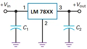
Fig. 1 shows a standard configuration of a fixed positive voltage IC regulator of 7800 series. Notice that it has three terminals labelled as input, output and ground. The last two digits (marked xx) in the part number designate the output voltage.
For example, IC 7805 is a +5 V regulator. Similarly IC 7812 is a +12 V regulator and IC 7815 is a +15 V regulator.
The capacitor C1 (typically 0.33 µF) is required only if the power supply filter is located more than 3 inches from the IC regulator. The capacitor C2 (typically 0.01 µF) acts basically as a line filter to improve transient response.
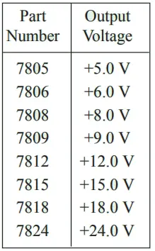
Fig. 2 shows the part number and the output voltage of 7800 series IC voltage regulators.
As seen from this figure, the 7800 series has IC regulators that can produce output voltages ranging from +5.0 to +24.0 volt. It may be carefully noted that although these regulators are designed primarily to produce fixed output voltage but they can be used with external components to obtain adjustable output voltage and current.
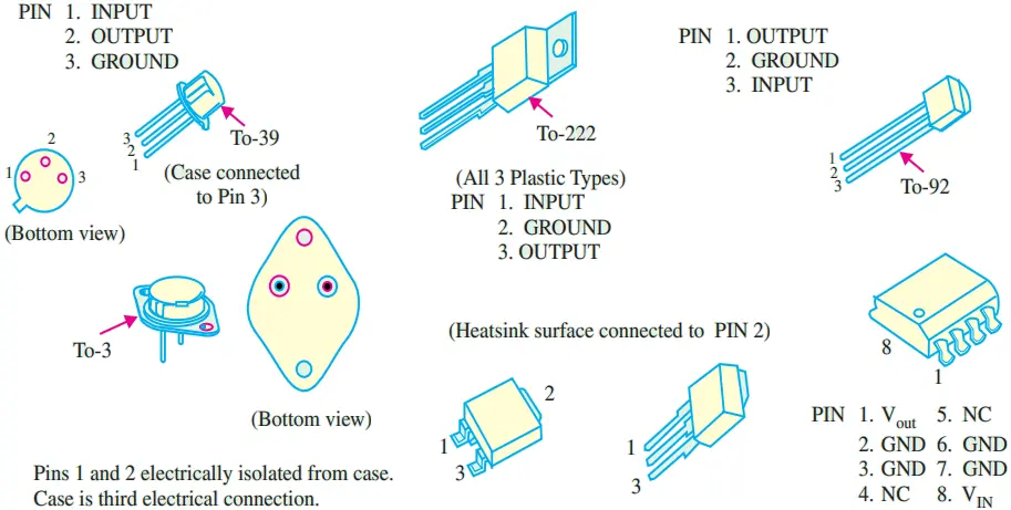
- The standard 7800 series can produce output current in excess of 1 A when used with adequate heat sink. It is available in aluminium can package TO-3 (indicated by K in the part number) and plastic package TO-220 (indicated by T in the part number).
- The 78L00 series can provide up to 100 mA and is available in TO-92 and metal TO-39 low profile packages.
- The 78M00 series can provide upto 0·5 A and is available in plastic TO-202 package.
It may be noted that the input voltage for the IC regulator must be at least 2 V above the output voltage. This is required in order to maintain regulation. The input voltage should not be more than 35 or 40 volts depending upon the part number.
The circuit inside all the IC regulators have internal thermal overload protection and short-circuit current-limiting features. Thermal overload in an IC regulator occurs whenever the internal power dissipation becomes excessive and the temperature of the device exceeds a certain value.
Fixed Negative Linear Voltage Regulators
The 7900 series is typical of three-terminal IC regulators that provide a fixed negative output voltage. This series is a negative-voltage counterpart of the 7800 series and shares most of the same features, characteristics and package types.
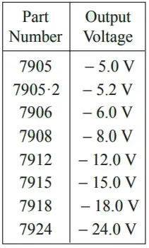
Fig. 3 shows the part numbers with corresponding output voltages that are available in 7900 series.
Adjustable Positive Output Linear Voltage Regulators
We can adjust the output voltage of 7800 series IC regulators higher than their fixed (or set) voltages. For example, the output voltage of 7805 can be adjusted higher than 5 V. But the performance and reliability of 7800 series to produce voltage higher than its fixed value is not considered to be good.
For this purpose, the LM 317 and LM 723 have been developed. Output voltage of these IC regulators can be adjusted over a wide range.
The output voltage of LM 317 can be adjusted from 1·2 V to 37 V, it can supply output current of 100 mA and is available in TO-92 package i.e., it is also a 3 terminal IC regulator.
On the other hand, the output voltage of LM 723 can be adjusted from 2 V to 37 V, it can supply output current of 150 mA without external transistor. But with the addition of external transistor, the output current capability can be increased in excess of 10 A. The LM 723 is available in dual-in-line package and in a metal can package.
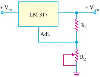
Fig. 4 shows the LM 317 connected to the external resistors R1 and R2 to produce an adjustable output voltage.
In operation, the LM 317 develops a constant 1·25 V reference voltage (VREF) between the output and adjustment terminal. This constant reference voltage produces a constant current, (IREF) through R1, regardless of the value of R2 Fig. 5.
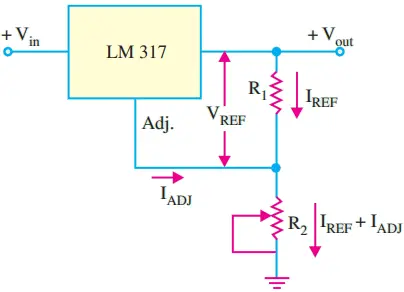
Notice that the value of current through R2 is the sum of IREF and IADJ, where IADJ is a very small current at the adjustment terminal. The value of IADJ is typically around 100 µA. It can be shown that the output voltage.
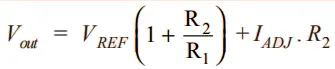
It is evident from the above equation that the output voltage is a function of R1 and R2. Usually the value of R1 is recommended to be around 220 Ω. Once the value of R1 is set, the output voltage is adjusted by varying R2.
Adjustable Negative Output Linear Voltage Regulators
A good example of this type of regulators is LM 337. The regulator is a negative output counterpart of LM 317. The LM 337 (like LM 317) requires two external resistors for adjustment of output voltage as shown in Fig. 6.
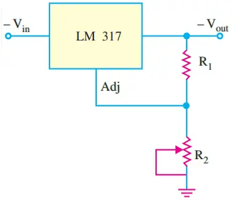
The output voltage can be adjusted anywhere from −1.2 V to − 37 V depending upon the external resistor values. The LM 723 can also be used as an adjustable negative output voltage regulator. The output voltage of this IC regulator can be adjusted anywhere from −2.0 V to −37 V depending upon the external resistor values.
Use of External Pass Transistor with Linear Voltage Regulators
We have already mentioned that a linear voltage regulator (7800 and 7900 series) is capable of delivering only a certain amount of output current to a load.
For example, the 7800 series regulators can handle a maximum output current of at least 1.3 A and typical 2.5 A. If the load current exceeds the maximum allowable value, there will be a thermal overload and the regulator will shut down. A thermal overload condition means that there is excessive power dissipation inside the regulator.
If an application requires a larger value of load current than the maximum current that the regulator can deliver, we will have to use an external pass transistor as shown in Fig. 6.
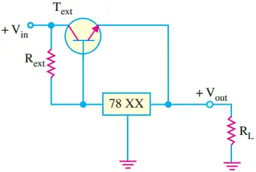
The value of Rext (current-sensing resistor) determines the value of current at which the external pass transistor (Text) begins to conduct because it sets the base-to-emitter voltage of the transistor.
As long as the current is less than the value set by Rext, the transistor Text is off and the regulator operates normally. This is because the voltage drop across Rext is less than 0.7 V (i.e. the base to emitter voltage required to turn Text on.
The value of Rext is determined by the equation Rext = 0.7 V/Imax where Imax is the maximum value of current that the voltage regulator is to handle internally.
When the current is sufficient to produce at least a 0.7 V drop across Rext, the transistor Text turns on and conducts any current in excess of Imax. The transistor Text will conduct current depending on the load requirement.
For example, if the total load current is 5 A and Imax was selected to be 1 A, then the external pass Transistor (Text) will conduct 4 A of current through it. It may be noted that the external pass transistor is a power transistor with heat sink that must be capable of handling a maximum power given by the equation,
Pext = Iext (Vin − Vout)
One major drawback of the circuit shown in Fig. 6 is that the external pass transistor is not protected from excessive current, such as would result from a shorted output. This drawback can be overcome by using an additional current limiting circuit as shown in Fig. 7. The operation of this circuit may be explained as follows.
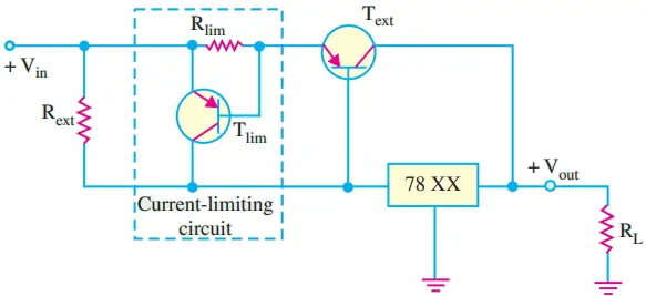
The current sensing resistor, Rlim sets the base-to-emitter voltage of Tlim. The base-to-emitter voltage of Text is now determined by ( VRext -VRlim) because they have opposite polarities. So for normal operation, the drop across Rext must be sufficient to overcome the opposing drop across Rlim.
If the current through Text exceeds a certain maximum value, (I ext(max)) because of a shorted output or a faulty load, the voltage across Rlim reaches 0.7 V and turns Tlim on. As a result, Tlim now conducts current away from Text and through the regulator. This forces a thermal overload to occur and shut down the regulator.
Remember, the IC voltage regulator circuitry is internally protected from thermal overload as part of its design. This way the external pass transistor is protected from excessive current.
Use of Linear Voltage Regulators as a Current Regulator
The 3-terminal linear voltage regulator can be used as a current source when an application requires that a constant current be supplied to a variable load. The basic circuit is shown in Fig. 8.
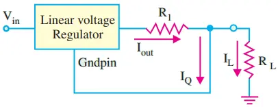
Here R1 is the current-setting resistor. The regulator provides a fixed output voltage, Vout between the ground terminal and the output terminal. However, it may be noted that the ground pin of the regulator is not connected to the circuit ground. The constant current supplied to the load, is given by the equation,
IL = Vout / RL + IQ
Usually the current, IQ is very small as compared to the output current and hence can be neglected, therefore
IL ≈ Vout / RL
For example, if we use 7805 regulator to provide a constant current of 1 A to a variable load, then R1 = 5/1 = 5 Ω
Please note that input voltage must be at least 2 V greater than the output voltage. Thus for 5 V regulator, Vin must be greater than 7 V.