Electronic Control of AC Motors
Efficient control of motors becomes critical where high precision, accuracy, reliability and faster response are of paramount importance. Electronic and digital controls are employed in such conditions.
Classes of Electronic A.C. Drives
AC motors, particularly, the squirrel-cage and wound-rotor induction motors as well as synchronous motors lend themselves well to electronic control of their speed and torque. Such a control is usually exercised by varying voltage and frequency. Majority of the electronic a.c. drives can be grouped under the following broad classes:-
- Static frequency changers like cyclo-converters which convert incoming high line frequency directly into the desired low load frequency. Cyclo-converters are used both for synchronous and squirrel-cage induction motors.
- Variable-voltage controllers which control the speed and torque by varying the a.c. voltage with the help of SCRs and gate turn-off- thyristors (GTOs).
- Rectifier-inverter systems with natural commutation.
- Rectifier-inverter systems with self-commutation.
Variable-frequency Speed Control of a SCIM
Fig. 1 shows a 3-phase SCIM connected to the outputs of three 3-phase cycloconverters. As seen, each cyclo-converter consists of two 3-phase thyristor bridges, each fed by the same 3-phase, 50-Hz line. The +R bridge generates the positive half-cycle for R-phase whereas −R generates the negative half.
The frequency of the cycloconverter output can be reduced to any value (even upto zero) by controlling the application of firing pulses to the thyristor gates (not shown in figure). This low frequency permits excellent speed control.
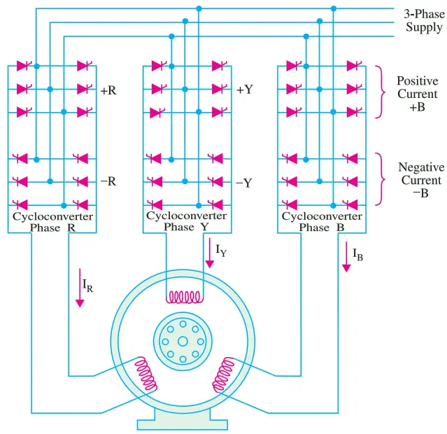
For example, the speed of a 4-pole induction motor can be varied from zero to 1200 rpm on a 50-Hz line by varying the output frequency of the cycloconverter from zero to 40 Hz. The stator voltage is adjusted in proportion to the frequency in order to maintain a constant flux in the motor.
This arrangement provides excellent torque/speed characteristics in all 4-quadrants including regenerative braking. However, such cycloconverter-fed motors run about 10°C hotter than normal and hence require adequate cooling.
A small part of the reactive power required by SCIM is provided by the cycloconverter, the rest being supplied by the 3-phase line.
Consequently, power factor is poor which makes cycloconverter drives feasible only on small and medium power induction motors.
Variable Voltage Speed Control of a SCIM
In this method, the speed of a SCIM (squirrel cage induction motor) is varied by varying the stator voltage with the help of three sets of SCRs connected back-to back.
The stator voltage is reduced by delaying the firing (or triggering) of the thyristors. If we delay the firing pulses by 100°, the voltage obtained is about 50% of the rated voltage which decreases the motor speed considerably.
Unfortunately, I2R losses are considerable due to distortion in voltage. Moreover, p.f. is also low due to large lag between the current and voltage. Hence, this electronic speed control method is feasible for motors rated below 15 kW but is quite suitable for small hoists which get enough time to cool off because of intermittent working.
Of course, p.f. can be improved by using special thyristors called gate turn-off thyristors (GTOs) which force the current to flow almost in phase with the voltage (or even lead it).
Speed Control of a SCIM with Rectifier Inverter System
A rectifier-inverter system with a d.c. link is used to control the speed of a SCIM (squirrel cage induction motor). The inverter used is a self-commuted type (different from a naturally commutated type) which converts d.c. power into a.c. power at a frequency determined by the frequency of the pulses applied to the thyristor gates.
The rectifier is connected to the 3-phase supply line whereas the inverter is connected to the stator of the SCIM. Two types of links are used:-
- Constant-current d.c. link —for speed control of individual motors.
- Constant-voltage d.c. link —for speed control of several motors.
As shown in Fig. 2, the constant-current link supplies constant current to the inverter which then feeds it sequentially (through proper switching sequence) to the three phases of the motor.
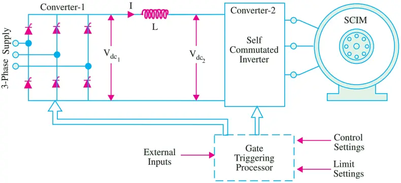
Similarly, the constant-voltage dc link provides a constant voltage to the inverter which is switched from one phase of the motor to the next in a proper sequence.
The arrangement of Fig. 2 gives speed control with high efficiency in all 4 quadrants in addition to the facility of regenerative braking. Heavy inertia loads can be quickly accelerated because motor develops full break-down torque right from the start.
The output frequency of the inverter varies over a range of 20:1 with a top frequency of about 1 kHz. The a.c. voltage supplied by the inverter is changed in proportion to the frequency so as to maintain the stator flux constant.
Consequently, d.c. link voltage Vdc1 has to be reduced as the motor speeds up. This is accomplished by increasing the firing angle of the thyristors in converter 1.
Unfortunately, this leads to increase in the reactive power drawn from the 3-phase line which results in poor power factor. To improve the p.f., use of capacitors is necessary.
The direction of rotation can be changed by altering the phase sequence of the pulses that trigger the gates of converter 2.
The 3-phase bridge rectifier produces d.c. voltage Vdc1 which is smoothened up by the LC filter before being applied to the inverter. The inverter successively switches its output ac voltage Vac to the three phases of the motor.
This voltage is varied in proportion to the frequency so as to maintain constant flux in the motor. Since, Vac depends on Vdc2 which itself depends on Vdc1, it is Vdc1 which is changed as frequency varies.
In this system, motor speed can be controlled from zero to maximum while developing full breakdown torque.
Chopper Speed Control of a WRIM
The speed of a WRIM (wound rotor induction motor) can be controlled by inserting three variable resistors in the rotor circuit. The all-electronic control of speed can be achieved by connecting a 3-phase bridge rectifier across the rotor terminals and then feed the rotor output to a single fixed resistor or R0 via a chopper (Fig. 3). The capacitor C supplies the high current pulses drawn by the chopper.
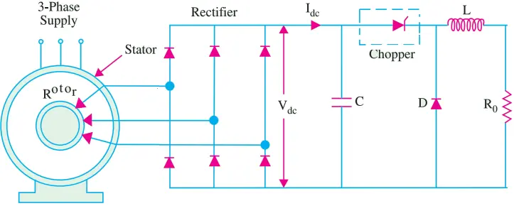
By varying the chopper on-time TON, the apparent resistance Ra across the bridge rectifier can be made either high or low. The value of apparent resistance is given by
Ra = R0/f2T2ON
Where f is the OFF/ON switching frequency of the chopper.
The resulting torque/speed characteristic is similar to the one obtained with a 3-phase rheostat.
Electronic Speed Control of Synchronous Motors
The speed of such motors may be controlled efficiently by using
- current-fed DC link and
- cycloconverter
Speed Control by Current-fed DC Link
As shown in Fig. 4, the typical circuit consists of three converters two of which are connected between the three-phase source and the synchronous motor whereas the third converter (bridge rectifier) supplies dc field excitation for the rotor.
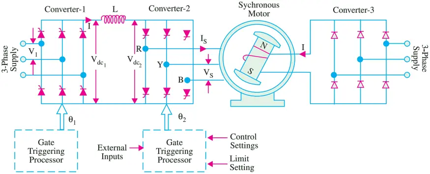
Converter-1 (C-1) acts as a controlled rectifier and feeds d.c. power to converter-2 (C-2). The converter-2 behaves as a naturally commutated inverter whose a.c. voltage and frequency are established by the motor.
The function of the smoothing inductor L is to maintain a ripple-free current in the d.c. link between the two converters. Converter-1 acts as a current source and controls I.
The converter-2 is naturally commutated by voltage Vs induced across motor terminals by its revolving magnetic flux. The revolving flux which depends on the stator currents and the d.c. field exciting current If1 is usually kept constant. Consequently, Vs is proportional to motor speed.
As regards various controls, information picked off from various points is processed in the gate triggering processors which then send out appropriate gate firing pulses to converters 1 and 2.
The processors receive information about the desired rotor speed, its actual speed, instantaneous rotor position, field current, stator voltage and current etc. The processors check whether these inputs represent normal or abnormal conditions and send appropriate gate firing pulses either to correct the situation or meet a specific demand.
Gate triggering of C-1 is done at line frequency (50 Hz) whereas that of C-2 is done at motor frequency. In fact, gate pulses of C-2 are controlled by rotor position which is sensed by position transducers mounted at the end of the shaft.
The motor speed can be increased by increasing either d.c. link current I or exciting current If . Now,
Vdc2 = 1.35 Vs cos α1 and
Vdc1 = 1.35 Vs cos α1
Where Vdc2 = d.c. voltage generated by C-2, Vdc1 = d.c. voltage supplied by C-1
α2 = firing angle of C-2, α1 = firing angle of C-1
The firing angle α1 is automatically controlled and supplies I which is sufficient to develop the required torque. This method of speed control is applied to motors ranging from 1 kW to several MW.
Permanent-magnet synchronous motors used in textile industry and brushless synchronous motors for nuclear reactor pumps are controlled by this method.
Synchronous Motor and Cycloconverter
As shown in Fig. 5, the arrangement consists of three cycloconverters connected to the three one phases of the synchronous motor and one controlled rectifier for supplying field exciting current If to the rotor. Each cycloconverter is composed of two three-phase bridges and supplies a single-phase output.
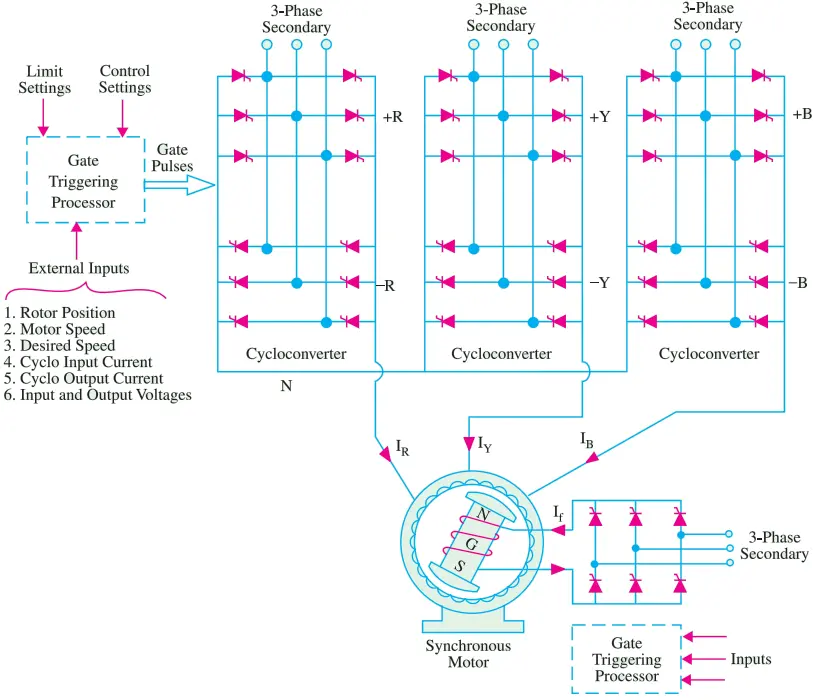
As is well known, a cycloconverter can directly convert a.c. power at higher frequency to one at a lower frequency. With a line frequency of 50 Hz, the cycloconverter output frequency can be varied from zero to 10 Hz.
The cycloconverters and the controlled rectifier function as current sources. The air-gap flux is kept constant by controlling the magnitude of the stator currents and exciting current If. By proper timing of gate pulses, motor can be made to operate at unity power factor.
The speed of cycloconverter-driven large slow-speed synchronous motors can be continuously varied from zero to 15 rpm.
Such low speeds permit direct drive of the ball mill without using a gear reducer. Such high-power low-speed systems are also being introduced as propeller drives on board the ships.