Construction, Working & Types of Synchros and Resolver
It is a general name for self-synchronizing machines which, when electrically energized and electrically interconnected, exert torques which cause two mechanically independent shafts either to run in synchronism or to make the rotor of one unit follow the rotor position of the other. They are also known by the trade names of selsyns and autosyns.
Synchros, in fact, are small cylindrical motors varying in diameter from 1.5 cm to 10 cm depending on their power output. They are low-torque devices and are widely used in control systems for transmitting shaft position information or for making two or more shafts to run in synchronism. If a large device like a robot arm is to be positioned, synchros will not work. Usually, a servomotor is needed for a higher torque.
Types of Synchros
There are many types of synchros but the four basic types used for position and error-voltage applications are as under:
- Control Transmitter (denoted by CX) – earlier called generator
- Control Receiver (CR) – earlier called motor
- Control-Transformer (CT) and
- Control Differential (CD).
It may be further subdivided into control differential transmitter (CDX) and control differential receiver (CDR). All of these synchros are single-phase units except the control differential which is of three-phase construction.
1. Control Transmitter (CX): Its constructional details are shown in Fig. 1 (a). It has a three-phase stator winding similar to that of a three-phase synchronous generator. The rotor is of the projecting-pole type using dumbell construction and has a single-phase winding.
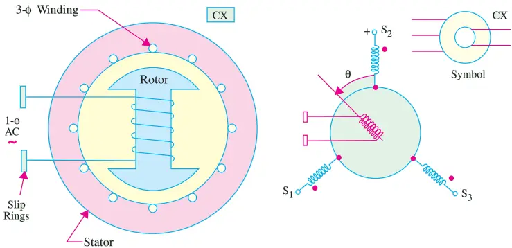
When a single-phase ac voltage is applied to the rotor through a pair of slip rings, it produces an alternating flux field along the axes of the rotor. This alternating flux induces three unbalanced single phase/voltage in the three stator windings by transformer action.
If the rotor is aligned with the axis of the stator winding 2, flux linkage of this stator winding is maximum and this rotor position is defined as the electrical zero.
In Fig. 1 (b), the rotor axis is displaced from the electrical zero by an angle displaced 120o apart.
2. Control Receiver: (CR) Its construction is essentially the same as that of the control transmitter shown in Fig. 1 (a). It has three stator windings and a single-phase salient-pole rotor. However, unlike a CX, a CR has a mechanical viscous damper on the shaft which permits CR rotor to respond without overshooting its mark.
In normal use, both the rotor and stator windings are excited with single-phase currents. When the field of the rotor conductors interacts with the field of the stator conductors, a torque is developed which produces rotation.
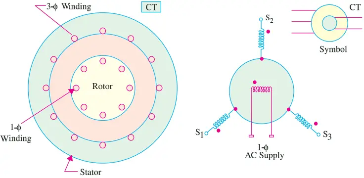
3. Control Transformer (CT): As shown in Fig. 1 (b) its stator has a three-phase winding whereas the cylindrical rotor has a single-phase winding. In this case, the electrical zero is defined as that position of the rotor that makes the flux linkage with winding 2 of the stator zero. This rotor position has been shown in Fig. 1 (b) and is different from that of a control transmitter.
4. Control Differential (CD): The differential synchro has a balanced three-phase distributed winding in both the stator and the rotor. Moreover, it has a cylindrical rotor as shown in Fig. 2.
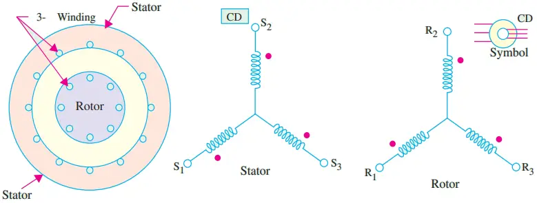
Although three-phase windings are involved, it must be kept in mind that these units deal solely with single-phase voltages. The three winding voltages are not polyphase voltages.
Normally, the three-phase voltages are identical in magnitude but are separated in phase by 120o. In synchros, these voltages are in phase but differ in magnitude because of their physical orientation.
Voltage Relations
Consider the control transmitter shown in Fig. 3. Suppose that its rotor winding is excited by a single-phase sinusoidal ac voltage of rms value Er and that rotor is held fast in its displaced position from the electrical zero.
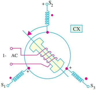
If K = stator turns/rotor turns, the rms voltage induced in the stator winding is E = KEr. However, if we assume K = 1, then E = Er.
The rms value of the induced emf in stator winding 2 when the rotor displacement is ‘a’ is given by
E2s = Er cos α.
Since the axis of the stator winding 1 is located 120o ahead of the axis of winding 2, the rms value of the induced emf in this winding is
E1s = Er cos (α – 120o).
In the same way since winding 3 is located behind the axis of winding 2 by 120o, the expression for the induced emf in winding 3 becomes
E3s = Er cos (α + 120o).
We can also find the values of terminal induced voltages as
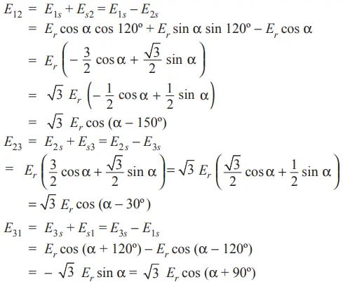
Applications of Synchros
The synchros are extensively used in servomechanism for
- torque transmission,
- error detection and
- for adding and subtracting rotary angles.
We will consider these applications one by one.
1. Torque Transmission: Synchros are used to transmit torque over a long distance without the use of a rigid mechanical connection. Fig. 4 represents an arrangement for maintaining alignment of two distantly-located shafts.
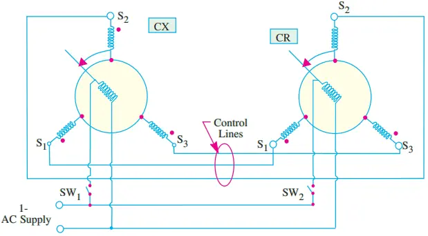
The arrangement requires a control transmitter (CX) and a control receiver (CR) which acts as a torque receiver. As CX is rotated by an angle α, CR also rotates through the same angle α. As shown, the stator windings of the two synchros are connected together and their rotors are connected to the same single-phase ac supply.
Working. Let us suppose that CX rotor is displaced by an angle α and switch SW1 is closed to energize the rotor winding. The rotor winding flux will induce an unbalanced set of three single-phase voltages (in time phase with the rotor voltage) in the CX stator phase windings which will circulate currents in the CR stator windings.
These currents produce the CR stator flux field whose axis is fixed by the angle α.
If the CR rotor winding is now energized by closing switch SW2, its flux field will interact with the flux field of the stator winding and thereby produce a torque.
This torque will rotate the freely-moving CR rotor to a position which exactly corresponds with the CT rotor i.e. it will be displaced by the same angle α as shown in Fig. 4.
It should be noted that if the two rotors are in the same relative positions, the stator voltages in the two synchros will be exactly equal and opposite. Hence, there will be no current flow in the two stator windings and so no torque will be produced and the system will achieve equilibrium.
If now, the transmitter rotor angle changes to a new value, then new set of voltages would be induced in the transmitter stator windings which will again drive currents through the receiver stator windings. Hence, necessary torque will be produced which will turn the CR rotor through an angle corresponding to that of the CT rotor.
That is why the transmitter rotor is called the master and the receiver rotor as the slave, because it follows its master.
It is worth noting that this master-slave relationship is reversible because when the receiver rotor is displaced through a certain angle, it causes the transmitter rotor to turn through the same angle.
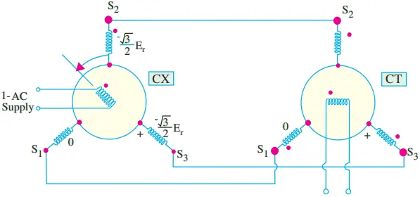
2. Error Detection: Synchros are also used for error detection in a servo control system. In this case, a command in the form of a mechanical displacement of the CX rotor is converted to an electrical voltage which appears at the CT rotor winding terminals which can be further amplified by an amplifier.
For this purpose, we require a CX synchro and a CT synchro as shown in Fig. 5. Only the CX rotor is energized from the single-phase ac voltage supply which produces an alternating air-gap flux field.
This time-varying flux field induces voltages in the stator windings whose values for α = 30o are as indicated in the Fig. 5.
The CX stator voltages supply magnetizing currents in the CT stator windings which, in turn, create an alternating flux field in their own air-gap.
The values of the CT stator phase currents are such that the air-gap flux produced by them induces voltages that are equal and opposite to those existing in the CX stator.
Hence, the direction of the resultant flux produced by the CX stator phase currents is forced to take a position which is exactly identical to that of the rotor axis of the CT.
If the CT rotor is assumed to be held fast in its electrical zero position as shown in Fig. 5, then the rms voltage induced in the rotor is given by E = Emax sin α, where Emax is the maximum voltage induced by the CT air-gap flux when coupling with the rotor windings is maximum and α is the displacement angle of the CT rotor.
In general, the value of the rms voltage induced in the CT rotor winding when the displacement of the CX rotor is αx and that of the CT rotor is αT is given by
E = Emax sin(αx − αT)
Control Differential Transmitter
It can be used to produce a rotation equal to the sum of difference of the rotations of two shafts. The arrangement for this purpose is shown in Fig. 6 (a).
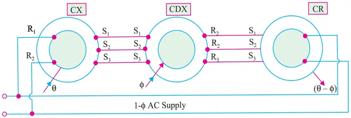
Here, a CDX is coupled to a control transmitter on one side and a control receiver on the other. The CX and CR rotor windings are energized from the same single-phase voltage supply
It has two inputs: Mechanical θ and Electrical φ and the output is Machnical (θ − φ). The mechanical input (θ) to CX is converted and applied to the CDX stator. With a rotor input (φ), the electrical output of the CDX is applied to the CR stator which provides the mechanical output (θ − φ).
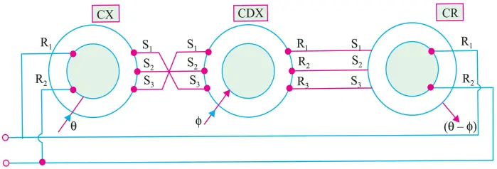
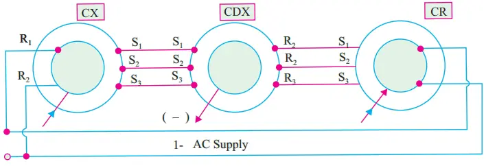
As shown in Fig. 6 (b), if any two stator connections between CX and CDX are transposed, the electrical input from CX to CDX becomes −θ, hence the output becomes (−θ − φ) = − (θ + φ).
Control Differential Receiver
In construction, it is similar to a CDX but it accepts two electrical input angles and provide the difference angle as a mechanical output (Fig. 7). The arrangement consists of two control transmitters coupled to a CDR.
The two control transmitters provide inputs to the CDX, one (θ) to the stator and the other (φ) to the rotor. The CDX output is the difference of the two inputs i.e. (θ − φ).
The Resolver
In many ways, it is similar to a synchro but differs from it in the following respects:-
- Electrical displacement between stator windings is 90o and not 120o.
- It has two stator windings and two rotor windings. (Fig. 8)
- Its input can be given either to the stator or to the rotor.
- They are usually not used as followers because their output voltage is put to further use.
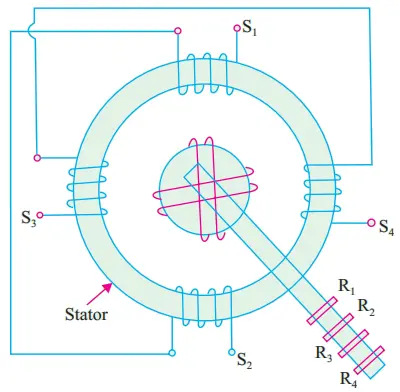
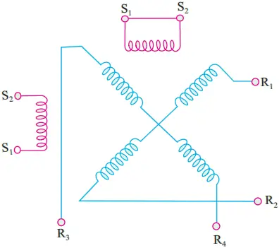
Construction: The main constructional features and the symbol for a resolver are shown in Fig. 8. There are two stator windings which are wound 90o apart. In most applications, only one stator winding is used, the other being short-circuited. The two rotor winding connections are brought out through slip rings and brushes.
Applications: Resolvers find many applications in navigation and height determination as shown in Fig. 9 (a) and (c) where Fig. 9 (b) provides the key.
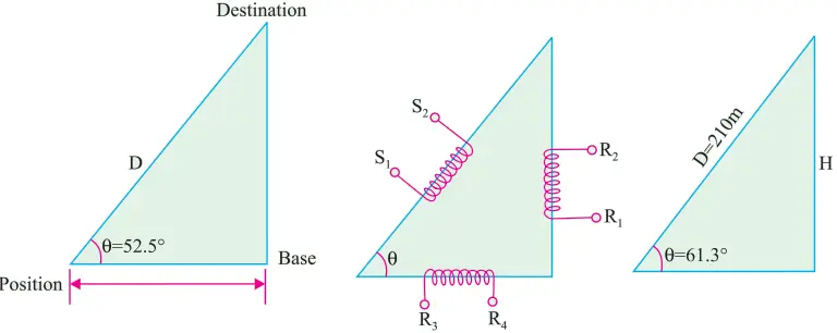
(i) Navigation Application: As shown in Fig. 39.25 (a), the purpose is to determine the distance D to the destination. Suppose the range R to a base station as found by a radar ranging device is 369 km.
The angle θ is also determined directly. If the amplifier scale is 4.5 V per 100 km, the range would be represented by 369 × (4.5/100) = 16.6 V.
Further suppose that angle θ is found to be 52.5o. Now, set the resolver at 52.5o and apply 16.6 V to rotor terminals R3 R4. The voltage which appears at terminals S1 S2 represents D.
If we assume K = stator turns / rotor turns = 1, the voltage available at S1 S2 will be = 16.6/cos 52.5o = 16.6/0.6088 = 27.3 V.
Since 4.5 V represents 100 km, 27.3 V represents 27.3 × 100/4.5 = 607 km.
(ii) Height Determination: Suppose the height H of a building is to be found. First of all, the oblique distance D to the top of the building is found by a range finder.
Let D = 210 m and the scale of the amplifier to the resolver stator be 9 V per 100 m. The equivalent voltage is 9 × 210/100 = 18.9 V. This voltage is applied to stator terminals is S1 S2 of the resolver.
Suppose the angle θ read from the resolver scale is 61.3o. The height of the building is given in the form of voltage which appears across the rotor terminals R1 R2.
Assuming stator/rotor turn ratio as unity and the same amplifier ratio for the rotor output, the voltage across R1 R2 = 18.9 × sin 61.3o = 16.6 V. Hence, H = 16.6 × 100/9 = 184 m.
It would be seen that in using the resolver, there is no need to go through trigonometric calculations because the answers come out directly.
This page helps a lot for my university examination
Thanks for appreciation.