Types of Protective Relays
In a power system consisting of generators, transformers, transmission and distribution circuits, it is inevitable that sooner or later some failure will occur somewhere in the system. When a failure occurs on any part of the system, it must be quickly detected and disconnected from the system. There are two principal reasons for it.
Firstly, if the fault is not cleared quickly, it may cause unnecessary interruption of service to the customers. Secondly, rapid disconnection of faulted apparatus limits the amount of damage to it and prevents the effects of fault from spreading into the system.
The detection of a fault and disconnection of a faulty section or apparatus can be achieved by using fuses or relays in conjunction with circuit breakers.
A fuse performs both detection and interruption functions automatically but its use is limited for the protection of low-voltage circuits only. For high voltage circuits (say above 3·3 kV), relays and circuit breakers are employed to serve the desired function of automatic protective gear.
The relays detect the fault and supply information to the circuit breaker which performs the function of circuit interruption. In this article, we shall focus our attention on the various types of relays and their increasing use for the protection of power system.
Protective Relays
A protective relay is a device that detects the fault and initiates the operation of the circuit breaker to isolate the defective element from the rest of the system.
The relays detect the abnormal conditions in the electrical circuits by constantly measuring the electrical quantities which are different under normal and fault conditions. The electrical quantities which may change under fault conditions are voltage, current, frequency and phase angle.
Through the changes in one or more of these quantities, the faults signal their presence, type and location to the protective relays. Having detected the fault, the relay operates to close the trip circuit of the breaker. This results in the opening of the breaker and disconnection of the faulty circuit.
Fundamental Requirements of Protective Relaying
The principal function of protective relaying is to cause the prompt removal from service of any element of the power system when it starts to operate in an abnormal manner or interfere with the effective operation of the rest of the system. In order that protective relay system may perform this function satisfactorily, it should have the following qualities:-
(1) selectivity (2) speed (3) sensitivity (4) reliability (5) simplicity (6) economy
(1) Selectivity. It is the ability of the protective system to select correctly that part of the system in trouble and disconnect the faulty part without disturbing the rest of the system. A well designed and efficient relay system should be selective i.e. it should be able to detect the point at which the fault occurs and cause the opening of the circuit breakers closest to the fault with minimum or no damage to the system.
This can be illustrated by referring to the single line diagram of a portion of a typical power system shown in Fig. 1. It may be seen that circuit breakers are located in the connections to each power system element in order to make it possible to disconnect only the faulty section.
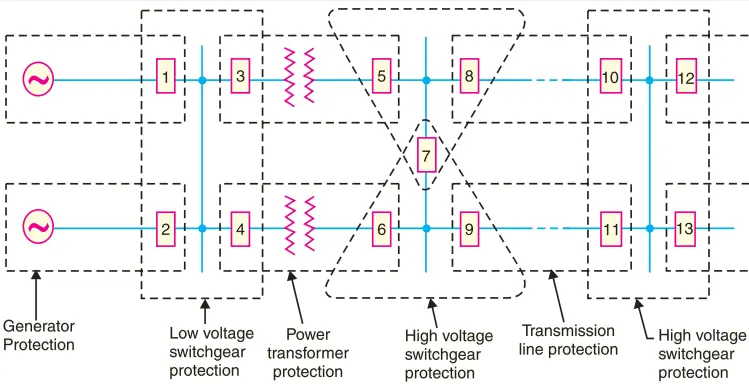
Thus, if a fault occurs at bus-bars on the last zone, then only breakers nearest to the fault viz. 10, 11, 12 and 13 should open. In fact, opening of any other breaker to clear the fault will lead to a greater part of the system being disconnected.
In order to provide selectivity to the system, it is a usual practice to divide the entire system into several protection zones. When a fault occurs in a given zone, then only the circuit breakers within that zone will be opened.
This will isolate only the faulty circuit or apparatus, leaving the healthy circuits intact. The system can be divided into the following protection zones:-
(a) generators (b) low-tension switchgear (c) transformers (d) high-tension switchgear (e) transmission lines
It may be seen in Fig. 1 that there is certain amount of overlap between the adjacent protection zones. For a failure within the region where two adjacent zones overlap, more breakers will be opened than the minimum necessary to disconnect the faulty section.
But if there were no overlap, a failure in the region between zones would not lie in either region and, therefore, no breaker would be opened. For this reason, a certain amount of overlap is provided between the adjacent zones.
(2) Speed. The relay system should disconnect the faulty section as fast as possible for the following reasons:-
- Electrical apparatus may be damaged if they are made to carry the fault currents for a long time.
- A failure on the system leads to a great reduction in the system voltage. If the faulty section is not disconnected quickly, then the low voltage created by the fault may shut down consumers’ motors and the generators on the system may become unstable.
- The high speed relay system decreases the possibility of development of one type of fault into the other more severe type.
(3) Sensitivity. It is the ability of the relay system to operate with low value of actuating quantity. Sensitivity of a relay is a function of the volt-amperes input to the coil of the relay necessary to cause its operation. The smaller the volt-ampere input required to cause relay operation, the more sensitive is the relay.
Thus, a 1 VA relay is more sensitive than a 3 VA relay. It is desirable that relay system should be sensitive so that it operates with low values of volt-ampere input.
(4) Reliability. It is the ability of the relay system to operate under the pre-determined conditions. Without reliability, the protection would be rendered largely ineffective and could even become a liability.
(5) Simplicity. The relaying system should be simple so that it can be easily maintained. Reliability is closely related to simplicity. The simpler the protection scheme, the greater will be its reliability.
(6) Economy. The most important factor in the choice of a particular protection scheme is the economic aspect. Sometimes it is economically unjustified to use an ideal scheme of protection and a compromise method has to be adopted.
As a rule, the protective gear should not cost more than 5% of total cost. However, when the apparatus to be protected is of utmost importance (e.g. generator, main transmission line etc.), economic considerations are often subordinated to reliability.
Basic Relays
Most of the relays used in the power system operate by virtue of the current and/or voltage supplied by current and voltage transformers connected in various combinations to the system element that is to be protected.
Through the individual or relative changes in these two quantities, faults signal their presence, type and location to the protective relays. Having detected the fault, the relay operates the trip circuit which results in the opening of the circuit breaker and hence in the disconnection of the faulty circuit.
Most of the relays in service on electric power system today are of electro-mechanical type. They work on the following two main operating principles:-
(1) Electromagnetic attraction (2) Electromagnetic induction
1. Electromagnetic Attraction Relays
Electromagnetic attraction relays operate by virtue of an armature being attracted to the poles of an electromagnet or a plunger being drawn into a solenoid. Such relays may be actuated by d.c. or a.c. quantities. The important types of electromagnetic attraction relays are:-
(i) Attracted armature type relay. Fig. 2 shows the schematic arrangement of an attracted armature type relay. It consists of a laminated electromagnet M carrying a coil C and a pivoted laminated armature. The armature is balanced by a counterweight and carries a pair of spring contact fingers at its free end.
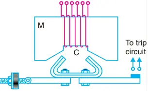
Under normal operating conditions, the current through the relay coil C is such that counterweight holds the armature in the position shown. However, when a short-circuit occurs, the current through the relay coil increases sufficiently and the relay armature is attracted upwards.
The contacts on the relay armature bridge a pair of stationary contacts attached to the relay frame. This completes the trip circuit which results in the opening of the circuit breaker and, therefore, in the disconnection of the faulty circuit.
The minimum current at which the relay armature is attracted to close the trip circuit is called pickup current. It is a usual practice to provide a number of tappings on the relay coil so that the number of turns in use and hence the setting value at which the relay operates can be varied.
(ii) Solenoid type relay. Fig. 3 shows the schematic arrangement of a solenoid type relay. It consists of a solenoid and movable iron plunger arranged as shown.
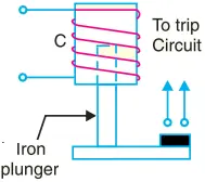
Under normal operating conditions, the current through the relay coil C is such that it holds the plunger by gravity or spring in the position shown. However, on the occurrence of a fault, the current through the relay coil becomes more than the pickup value, causing the plunger to be attracted to the solenoid. The upward movement of the plunger closes the trip circuit, thus opening the circuit breaker and disconnecting the faulty circuit.
(iii) Balanced beam type relay. Fig. 4 shows the schematic arrangement of a balanced beam type relay. It consists of an iron armature fastened to a balance beam.
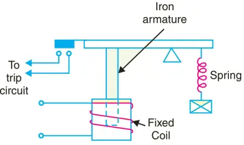
Under normal operating conditions, the current through the relay coil is such that the beam is held in the horizontal position by the spring.
However, when a fault occurs, the current through the relay coil becomes greater than the pickup value and the beam is attracted to close the trip circuit. This causes the opening of the circuit breaker to isolate the faulty circuit.
2. Induction Relays
Electromagnetic induction relays operate on the principle of induction motor and are widely used for protective relaying purposes involving a.c. quantities. They are not used with d.c. quantities owing to the principle of operation.
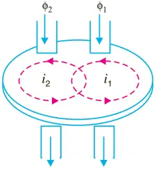
An induction relay essentially consists of a pivoted aluminium disc placed in two alternating magnetic fields of the same frequency but displaced in time and space. The torque is produced in the disc by the interaction of one of the magnetic fields with the currents induced in the disc by the other (Fig. 5).
The following three types of structures are commonly used for obtaining the phase difference in the fluxes and hence the operating torque in induction relays:-
(i) shaded-pole structure (ii) watthour-meter or double winding structure (iii) induction cup structure
(i) Shaded-pole structure. The general arrangement of shaded-pole structure is shown in Fig. 6. It consists of a pivoted aluminium disc free to rotate in the air-gap of an electromagnet. One-half of each pole of the magnet is surrounded by a copper band known as shading ring.
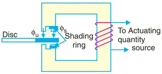
The alternating flux φs in the shaded portion of the poles will, owing to the reaction of the current induced in the ring, lag behind the flux φu in the un-shaded portion by an angle α.
These two a.c. fluxes differing in phase will produce the necessary torque to rotate the disc. The driving torque T is given by;
T ∝ φs φu sin α
Assuming the fluxes φs and φu to be proportional to the current I in the relay coil,
T ∝ I2 sin α
This shows that driving torque is proportional to the square of current in the relay coil.
(ii) Watthour-meter structure. This structure gets its name from the fact that it is used in watthour meters. The general arrangement of this type of relay is shown in Fig. 7. It consists of a pivoted aluminium disc arranged to rotate freely between the poles of two electromagnets.
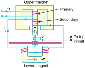
The upper electromagnet carries two windings; the primary and the secondary. The primary winding carries the relay current I1 while the secondary winding is connected to the winding of the lower magnet. The primary current induces e.m.f. in the secondary and so circulates a current I2 in it. The flux φ2 induced in the lower magnet by the current in the secondary winding of the upper magnet will lag behind φ1 by an angle α.
The two fluxes φ1and φ2 differing in phase by α will produce a driving torque on the disc proportional to φ1φ2 sin α.
An important feature of this type of relay is that its operation can be controlled by opening or closing the secondary winding circuit. If this circuit is opened, no flux can be set by the lower magnet however great the value of current in the primary winding may be and consequently no torque will be produced. Therefore, the relay can be made inoperative by opening its secondary winding circuit.
(iii) Induction cup structure. Fig. 8 shows the general arrangement of an induction cup structure. It most closely resembles an induction motor, except that the rotor iron is stationary, only the rotor conductor portion being free to rotate. The moving element is a hollow cylindrical rotor which turns on its axis.
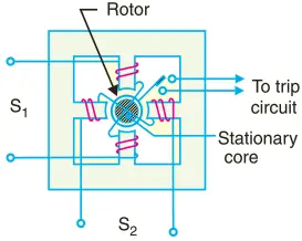
The rotating field is produced by two pairs of coils wound on four poles as shown. The rotating field induces currents in the cup to provide the necessary driving torque.
If φ1 and φ2 represent the fluxes produced by the respective pairs of poles, then torque produced is proportional to φ1φ2 sin α. Where α is the phase difference between the two fluxes.
A control spring and the back stop for closing of the contacts carried on an arm are attached to the spindle of the cup to prevent the continuous rotation. Induction cup structures are more efficient torque producers than either the shaded-pole or the watthour meter structures. Therefore, this type of relay has very high speed and may have an operating time less then 0·1 second.
Relay Timing
An important characteristic of a relay is its time of operation. By ‘the time of operation’ is meant length of the time from the instant when the actuating element is energised to the instant when the relay contacts are closed. Sometimes it is desirable and necessary to control the operating time of a relay. For this purpose, mechanical accessories are used with relays.
(1) Instantaneous relay. An instantaneous relay is one in which no intentional time delay is provided. In this case, the relay contacts are closed immediately after current in the relay coil exceeds the minimum calibrated value.
Although there will be a short time interval between the instant of pickup and the closing of relay contacts, no intentional time delay has been added. The instantaneous relays have operating time less than 0·1 second.
The instantaneous relay is effective only where the impedance between the relay and source is small compared to the protected section impedance.
The operating time of instantaneous relay is sometimes expressed in cycles based on the power-system frequency e.g. one-cycle would be 1/50 second in a 50-cycle system.
(2) Inverse-time relay. An inverse-time relay is one in which the operating time is approximately inversely proportional to the magnitude of the actuating quantity.
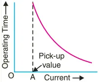
Fig. 9 shows the time-current characteristics of an inverse current relay. At values of current less than pickup, the relay never operates. At higher values, the time of operation of the relay decreases steadily with the increase of current. The inverse-time delay can be achieved by associating mechanical accessories with relays.
- In an induction relay, the inverse-time delay can be achieved by positioning a permanent magnet (known as a drag magnet) in such a way that relay disc cuts the flux between the poles of the magnet. When the disc moves, currents set up in it produce a drag on the disc which slows its motion.
- In other types of relays, the inverse time delay can be introduced by oil dashpot or a time-limit fuse.
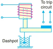
Fig. 10 shows an inverse time solenoid relay using oil dashpot. The piston in the oil dashpot attached to the moving plunger slows its upward motion.
At a current value just equal to the pickup, the plunger moves slowly and time delay is at a maximum. At higher values of relay current, the delay time is shortened due to greater pull on the plunger.
The inverse-time characteristic can also be obtained by connecting a time-limit fuse in parallel with the trip coil terminals as shown in Fig. 11.
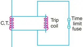
The shunt path formed by time-limit fuse is of negligible impedance as compared with the relatively high impedance of the trip coil. Therefore, so long as the fuse remains intact, it will divert practically the whole secondary current of CT from the trip oil.
When the secondary current exceeds the current carrying capacity of the fuse, the fuse will blow and the whole current will pass through the trip coil, thus opening the circuit breaker.
The time-lag between the incidence of excess current and the tripping of the breaker is governed by the characteristics of the fuse. Careful selection of the fuse can give the desired inverse-time characteristics, although necessity for replacement after operation is a disadvantage.
(3) Definite time lag relay. In this type of relay, there is a definite time elapse between the instant of pickup and the closing of relay contacts. This particular time setting is independent of the amount of current through the relay coil; being the same for all values of current in excess of the pickup value.
It may be worthwhile to mention here that practically all inverse-time relays are also provided with definite minimum time feature in order that the relay may never become instantaneous in its action for very long overloads.
Important Terms
It is desirable to define and explain some important terms much used in connection with relays.
(1) Pick-up current. It is the minimum current in the relay coil at which the relay starts to operate. So long as the current in the relay is less than the pick-up value, the relay does not operate and the breaker controlled by it remains in the closed position.
However, when the relay coil current is equal to or greater than the pickup value, the relay operates to energise the trip coil which opens the circuit breaker.
(2) Current setting. It is often desirable to adjust the pick-up current to any required value. This is known as current setting and is usually achieved by the use of tappings on the relay operating coil. The taps are brought out to a plug bridge as shown in Fig. 12.
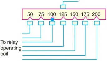
The plug bridge permits to alter the number of turns on the relay coil. This changes the torque on the disc and hence the time of operation of the relay. The values assigned to each tap are expressed in terms of percentage full-load rating of C.T. with which the relay is associated and represents the value above which the disc commences to rotate and finally closes the trip circuit.
∴ Pick-up current = Rated secondary current of C.T. × Current setting
For example, suppose that an overcurrent relay having current setting of 125% is connected to a supply circuit through a current transformer of 400/5. The rated secondary current of C.T. is 5 amperes. Therefore, the pick-up value will be 25% more than 5 A i.e. 5 × 1·25 = 6·25 A. It means that with above current setting, the relay will actually operate for a relay coil current equal to or greater than 6·25 A.
The current plug settings usually range from 50% to 200% in steps of 25% for overcurrent relays and 10% to 70% in steps of 10% for earth leakage relays. The desired current setting is obtained by inserting a plug between the jaws of a bridge type socket at the tap value required.
(3) Plug-setting multiplier (P.S.M.). It is the ratio of fault current in relay coil to the pick-up current i.e.
P.S.M. = Fault current in relay coil ÷ Pick-up current
= Fault current in relay coil ÷ (Rated secondary current of CT × Current setting)
For example, suppose that a relay is connected to a 400/5 current transformer and set at 150%. With a primary fault current of 2400 A, the plug-setting multiplier can be calculated as under:-
Pick-up value = Rated secondary current of CT × Current setting
= 5 × 1·5 = 7·5 A
Fault current in relay coil = 2400 (5/400) = 30 A
∴ P.S.M. = 30/7·5 = 4
(4) Time-setting multiplier. A relay is generally provided with control to adjust the time of operation. This adjustment is known as time-setting multiplier. The time-setting dial is calibrated from 0 to 1 in steps of 0.05 sec (see Fig. 13).
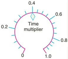
These figures are multipliers to be used to convert the time derived from time/P.S.M. curve into the actual operating time.
Thus if the time setting is 0·1 and the time obtained from the time/P.S.M. curve is 3 seconds, then actual relay operating time = 3 × 0·1 = 0·3 second.
For instance, in an induction relay, the time of operation is controlled by adjusting the amount of travel of the disc from its reset position to its pickup position. This is achieved by the adjustment of the position of a movable backstop which controls the travel of the disc and thereby varies the time in which the relay will close its contacts for given values of fault current.
A so-called “time dial” with an evenly divided scale provides this adjustment. The actual time of operation is calculated by multiplying the time setting multiplier with the time obtained from time/P.S.M. curve of the relay.
Time/P.S.M. Curve
Fig. 14 shows the curve between time of operation and plug setting multiplier of a typical relay. The horizontal scale is marked in terms of plug-setting multiplier and represents the number of times the relay current is in excess of the current setting.
The vertical scale is marked in terms of the time required for relay operation. If the P.S.M. is 10, then the time of operation (from the curve) is 3 seconds. The actual time of operation is obtained by multiplying this time by the time-setting multiplier.
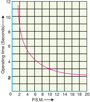
It is evident from Fig. 14 that for lower values of over-current, time of operation varies inversely with the current but as the current approaches 20 times full-load value, the operating time of relay tends to become constant. This feature is necessary in order to ensure discrimination on very heavy fault currents flowing through sound feeders.
Calculation of Relay Operating Time
In order to calculate the actual relay operating time, the following things must be known:-
(a) Time/P.S.M. curve (b) Current setting (c) Time setting (d) Fault current (e) Current transformer ratio
The procedure for calculating the actual relay operating time is as follows:-
- Convert the fault current into the relay coil current by using the current transformer ratio.
- Express the relay current as a multiple of current setting i.e. calculate the P.S.M.
- From the Time/P.S.M. curve of the relay, read off the time of operation for the calculated P.S.M.
- Determine the actual time of operation by multiplying the above time of the relay by time-setting multiplier in use.
EXAMPLE
Determine the time of operation of a 5-ampere, 3-second over-current relay having a current setting of 125% and a time setting multiplier of 0·6 connected to supply circuit through a 400/5 current transformer when the circuit carries a fault current of 4000 A. Use the curve shown in Fig. 14.
SOLUTION
Rated secondary current of C.T. = 5 A
Pickup current = 5 × 1·25 = 6·25
A Fault current in relay coil = 4000(5/400) = 50 A
∴ Plug-setting multiplier (P.S.M.) = 50/6.25 = 8
Corresponding to the plug-setting multiplier of 8 (See Fig. 14), the time of operation is 3.5 seconds.
∴ Actual relay operating time = 3·5 × Time-setting = 3·5 × 0·6 = 2·1 seconds