The induction motor rotates due to the rotating magnetic field in induction motor, which is produced by the stator winding in the air gap between the stator and the rotor. The stator has a three phase stationary winding which can be either star connected or delta connected.
Whenever the AC supply is connected to the stator windings, line currents IR, IY, and IB start flowing. These line currents have phase difference of 120o with respect to each other. Due to each line current, a sinusoidal flux is produced in the air gap. These fluxes have the same frequency as that of the line currents, and they also have the same phase difference of 120o with respect to each other.
Let the flux produced by the line currents IR, IB, IY be φR, φB, φY respectively.

Mathematically, they are represented as follows:
φR = φm sin ωt = φm sin θ
φB = φm sin (ωt – 120o) = φm sin (θ – 120o)
φY = φm sin (ωt – 240o) = φm sin (θ – 240o)
The effective or total flux (ɸT) in the air gap is equal to the phasor sum of the three components of fluxes ɸR, ɸY and, ɸB.
Therefore, ɸT = ɸR + ɸY + ɸB
Prove that RMF in Induction Motor is Rotating
To prove that this RMF is rotating we will:
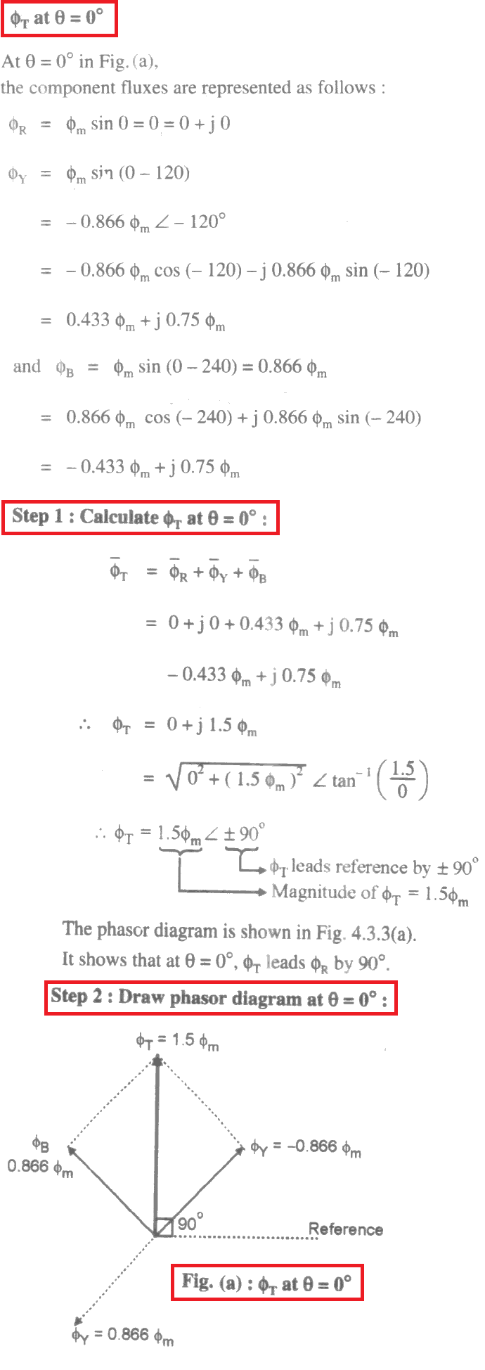
Step 1: We will find the values of total flux ɸT for different values of θ such as 0, 60, 120 , 180 ….. 360o.
Step 2: For every value of θ in step 1, we will draw the phasor diagrams.
By observing these phasor digrams you can understand easily that ɸT keep shifting its position from 90o to 30o to – 30o to – 90o and so on. In other words ɸT rotates in the clock wise direction.
We will use the phasor ɸR as the reference phasor i.e. all the angles are drawn with respect to this phasor.
ɸT at θ = 0o

ɸT at θ = 60o

ɸT at θ =120o

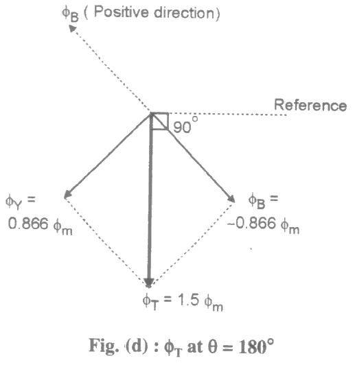
ɸT at θ =180o
Similarly we can prove that ɸT at θ =180o is given by,
ɸT = 1.5ɸm ∠ – 90o
The phasor diagram for θ =180o is shown in Figure (d).

Speed of Rotating Magnetic Field in Induction Motor
The magnetic field in three phase induction motor (RMF) rotates at a constant speed called synchronous speed (Ns), which is given by,
NS = 120f1/P RPM
where f1 = Frequency of stator supply
P = Number of poles of motor.
Direction of Rotating Magnetic Field
The direction of rotating magnetic field depends upon the phase sequence of the AC supply connected across the stator winding. If we interchange any two phases of the AC supply, we will get new phase sequence, then the direction of rotating magnetic field in three phase induction motor will reverse. It will start rotating in reverse direction and so does the rotor.
Since a stator and its winding of three phase induction motor is the same as that of a synchronous motor. So all above discussion about RMF in induction motor is the same for RMF in synchronous motor also.
Three Phase Induction Motor | All Posts
- Induction Motor MCQ
- Three Phase Induction Motor Construction
- Three Phase Induction Motor Working Principle
- Induction Motor Slip
- Torque Formula for Induction Motor
- Torque Slip Characteristics of Induction Motor
- Losses in Induction Motor
- Induction Motor Tests
- Starting Methods of Induction Motor
- Double Squirrel Cage Induction Motor
- Speed Control of 3 Phase Induction Motor
- What is a variable frequency drive?
- Autotransformer Starter Working Principle
- Thermal Overload Relay Working
- Induction Motor Equivalent Circuit
- Linear Induction Motor Working | Applications
© https://yourelectricalguide.com/ rotating magnetic field in induction motor.